Energy-saving ship capable of efficiently decomposing resistance

A resistance and high-efficiency technology, applied in ship propulsion, ship parts, ship construction, etc., can solve the problems of small navigation resistance, easy overturning of ships, difficult maintenance or replacement of propellers, etc., and achieve the effect of ensuring navigation and low navigation resistance.

Inactive Publication Date: 2016-01-06
韦振秋 +2
View PDF7 Cites 5 Cited by
  • Summary
  • Abstract
  • Description
  • Claims
  • Application Information

AI Technical Summary

Problems solved by technology

[0004] The technical problem to be solved by the present invention is to provide a high-efficiency decomposition resistance energy-saving ship with small sailing resistance, and at the same time eliminate the risk of the ship being prone to capsize when sailing at high speed and making a sharp turn, and solve the problem of propeller maintenance or replacement when the ship is in the water area difficult question

Method used


Image

  • Energy-saving ship capable of efficiently decomposing resistance
  • Energy-saving ship capable of efficiently decomposing resistance
  • Energy-saving ship capable of efficiently decomposing resistance

Examples


Embodiment 1

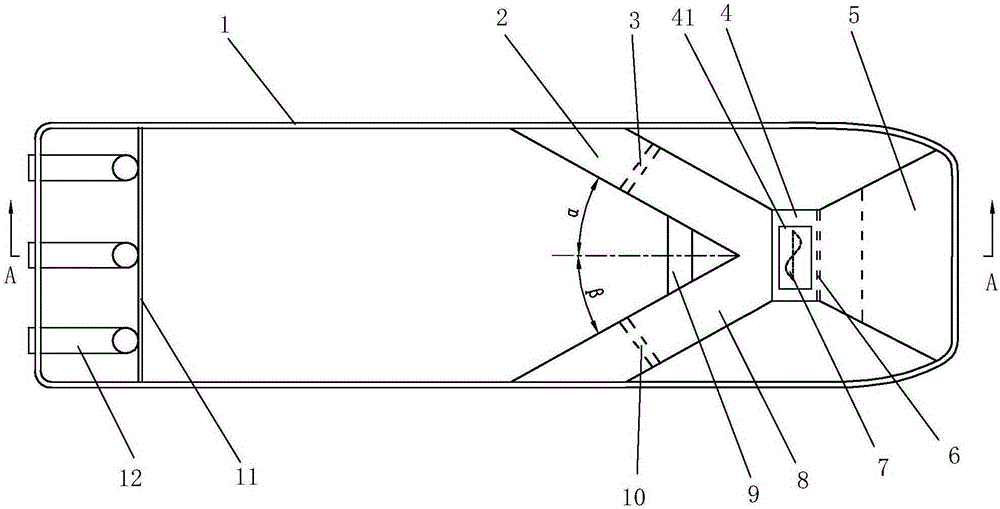
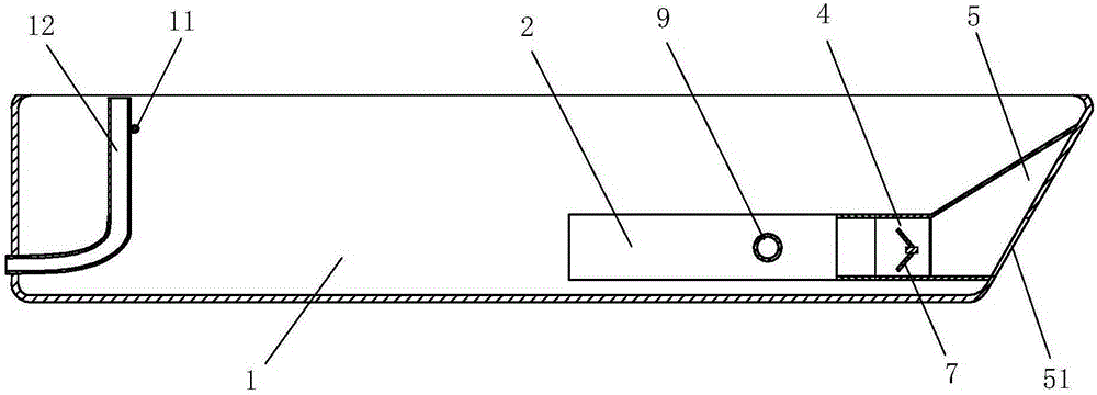
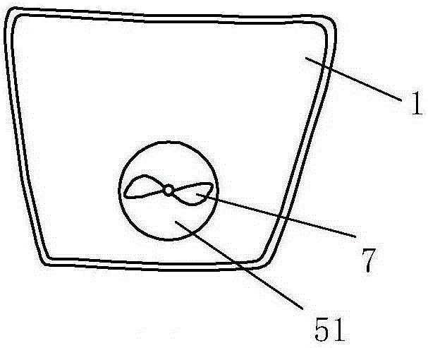
[0026] Embodiment 1: A kind of high-efficiency decomposition resistance energy-saving ship, such as Figure 1-Figure 3 As shown, it includes a hull 1 and a propeller, and the propeller includes a DC propeller 7, and the bilge of the hull 1 is provided with a bow suction horn 5, a connecting pipe 4, a left drainage channel 2 and a right drainage channel 8 , the DC propeller 7 is installed in the connecting pipe 4, the connecting pipe is connected and communicated with the bow water suction bell mouth 5, the water inlets of the left drainage channel 2 and the right drainage channel 8 are connected and communicated with the connecting pipeline 4, and the left drainage The water outlet of the channel is located on the left side of the hull, and the water outlet of the right drainage channel is located on the right side of the hull. A left valve 3 is arranged in the left drainage channel. The left valve is used to control the opening and closing of the left drainage channel 2 and ad...

Embodiment 2

[0030] Embodiment 2: A kind of high-efficiency decomposition resistance energy-saving ship, such as Figure 4As shown, its basic structure is the same as that of Embodiment 1, the difference is that the propeller also includes a left vortex propeller 13 and a right vortex propeller 16, and the left vortex propeller 13 is installed on the bow water suction horn 5 on the left side and communicates with the left drainage channel 2 through the left pipeline 15, and the right vortex propeller 16 is installed on the right side of the water suction bell mouth 5 of the bow and communicates with the right drainage channel 8 through the right pipeline 18. The water inlet of the left vortex propeller 13 is provided with a water inlet and outlet valve 20 of the left vortex propeller, and a valve I 14 is arranged in the left pipeline 15, and the valve I is used to control the opening and closing of the left pipeline 15 and adjust the water flow. The vortex propeller 16 is provided with a r...


PUM


Abstract

The invention relates to an energy-saving ship capable of efficiently decomposing resistance. The energy-saving ship comprises a ship body and a direct current propeller and is characterized in that a bilge of a hull is provided with a bow water absorbing horn mouth, a connecting pipeline and left and right water drain channels. The direct current propeller is installed in the connecting pipeline. The connecting pipeline is connected and communicated with the bow water absorbing horn mouth, water inlets of the left and right water drain channels are connected and communicated with the connecting pipeline, water outlets of the left and right water drain channels are located in the left side and the right side of the hull respectively, a left valve and a right valve are arranged in the left and right water drain channels respectively, and multiple balancing air pipes are arranged at the tail in the hull. As the bow water absorbing horn mouth and the balancing air pipes are arranged, the maximum resistance generated by counter impact of the bow and water and the resistance formed by vacuum in the stern in the ship sailing process can be efficiently decomposed, and the ship has the advantage of low sailing resistance; the risk that the ship is prone to capsizing when being steered abruptly in the high-speed sailing process is eliminated; the problem that because the ship is located in water, the propeller is difficult to maintain or replace is solved.

Description

technical field [0001] The invention relates to a ship, in particular to an energy-saving ship with high-efficiency decomposition resistance. Background technique [0002] The propellers of traditional ships and the rudders for controlling the direction are all arranged at the stern. The traditional ships of this structure have the following disadvantages: 1. When the ship advances, the bow and the water are against each other, which brings resistance to the forward movement of the ship and makes the waves overturn. The greater the resistance, the greater the resistance; 2. When the ship moves forward, the stern forms a vacuum suction, which increases the resistance to the forward movement of the ship. The faster the speed of the ship, the greater the vacuum suction. The force generated by the flow direction of the ship is in the same direction as the centrifugal force of the hull, so that the hull tilts outward, and there is a danger of capsizing; 4. When the propeller brea...

Claims


Application Information

Patent Timeline
Patent Type & Authority Applications(China)
IPC IPC(8): B63H11/02
Inventor 韦振秋韦海明韦海萍
Owner 韦振秋
Why Eureka
Try Eureka