Method for replacing ladle turret rotary arm of continuous casting machine

The technology of a large-bag rotary table and a replacement method is applied in the field of replacing the rotary arm of a large-bag rotary table of a continuous casting machine, which can solve the problems of time-consuming and labor-intensive, and achieve the effect of good balance effect, reducing influence and improving maintenance efficiency.

Active Publication Date: 2016-01-06
ANHUI MA STEEL EQUIP MAINTENANCE CO LTD
View PDF10 Cites 4 Cited by
  • Summary
  • Abstract
  • Description
  • Claims
  • Application Information

AI Technical Summary

Problems solved by technology

[0005] Aiming at the problem of high labor intensity and time-consuming replacement of the rotary arm of the ladle rotary table of the continuous casting machine in the prior art, the present invention provides a method for replacing the rotary arm of the ladle rotary table of the continuous casting machine

Method used


Image

  • Method for replacing ladle turret rotary arm of continuous casting machine
  • Method for replacing ladle turret rotary arm of continuous casting machine
  • Method for replacing ladle turret rotary arm of continuous casting machine

Examples


Embodiment 1

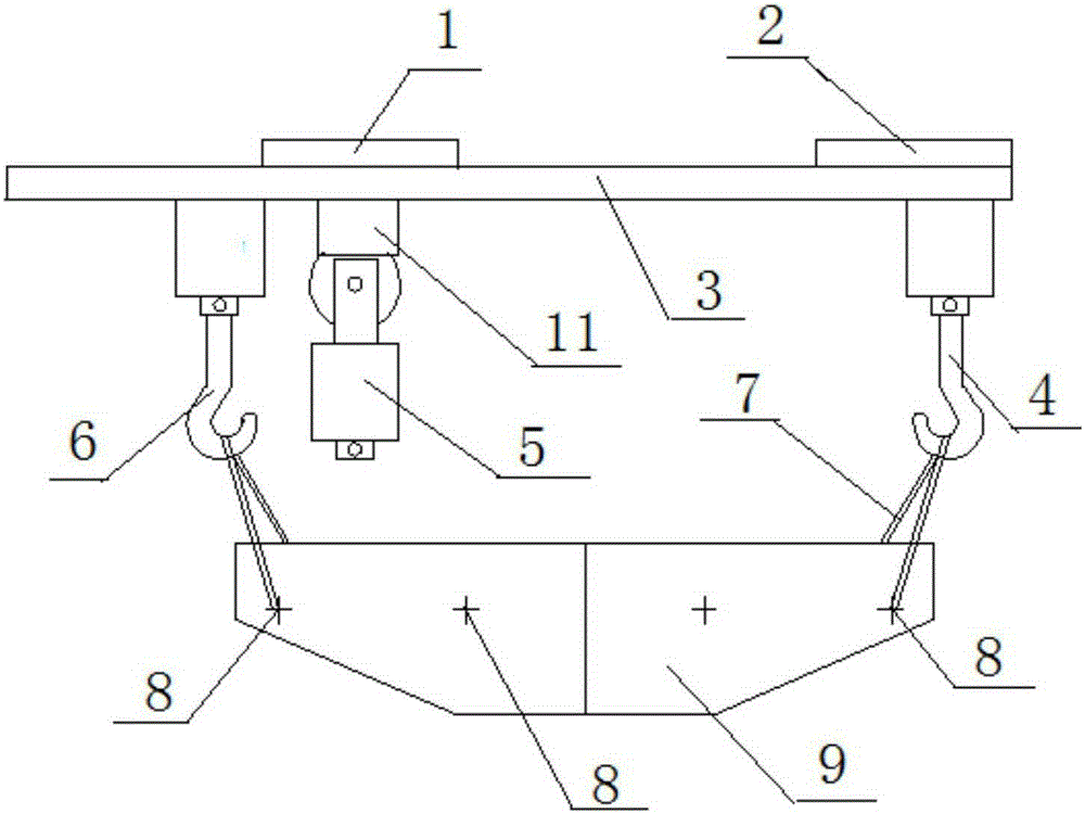
[0041] The total weight of the rotary arm of the ladle rotary table of the continuous casting machine in this embodiment is 44T. The difficulty of this overhaul lies in hoisting the rotary arm, transporting it in the air, and landing it on the ground. Since the slewing arm of the bale turntable is in the dead angle position of the driving, it is impossible to complete the lifting work with a one-span driving. This hoisting method adopts the method of hoisting the slewing arm at the same time with two-span cranes for hoisting and installation. Hoisting traction rope 7 is a steel wire rope, specification: 4 wire ropes of φ 39mm*9 meters, and antiskid and protection measures are done well. The replacement steps are:

[0042] A. Installation of fixing parts: Evenly distribute and detachably fix the fixing parts 8 in the length direction of the rotary arm 9 of the ladle rotary table of the continuous casting machine;

[0043] B. Hoisting between two spans: such as figure 1 As sh...

Embodiment 2

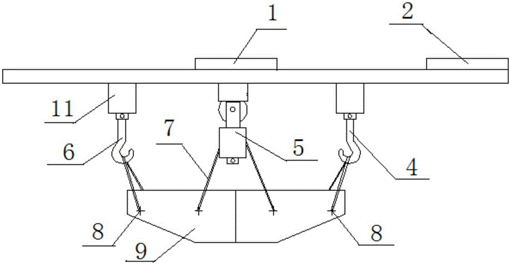
[0050] The basic steps of the method for replacing the rotary arm of the ladle turret of the continuous casting machine in this embodiment are the same as those of Embodiment 1. The improvement is that in step A, the fixing part 8 is a D-shaped lifting lug, which is rotated on the ladle turret of the continuous casting machine. There are four on the front and back sides of the arm 9, and they are symmetrically arranged front and back. The D-shaped lifting lug structure is convenient for lifting and translation, and is simple and practical. ,Such as Figure 4 As shown, when the main hook 5 of the molten steel straddling vehicle is in use, the lower hook is disassembled, leaving only the balance beam 51 of the main hook of the molten steel straddling vehicle, which effectively prevents the lifting stroke of the main hook of the molten steel straddling vehicle from being affected by it. The car owner's hook 4 moves forward, backward, left and right on the guide rail 3 through the...

Embodiment 3

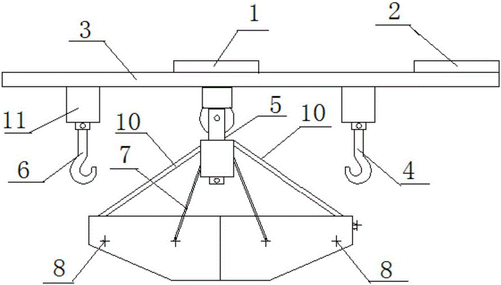
[0052] The basic steps of the method for replacing the rotary arm of the ladle rotary table of the continuous casting machine in this embodiment are the same as those in Embodiment 2, and the improvement is that in step C, the auxiliary hook 6 of the molten steel straddle carriage and the main hook 4 of the continuous casting straddle carriage are passed through the traveling mechanism 11 in the The guide rail 3 translates back and forth, left and right, and the two-span cranes are synchronously translated by the PLC to control the traveling mechanism 11 to move the rotary arm 9 of the ladle turntable of the continuous casting machine to the position directly below the main hook 5 of the molten steel straddle carriage. In step E, the balancing mechanism 10 is a 10-ton electric hoist; the PLC controls the traveling mechanism 11 to perform precise translation, and the positioning effect is good, so that the molten steel cross-travel hook 6 and the continuous casting cross-travel m...


PUM


Abstract

The invention discloses a method for replacing a ladle turret rotary arm of a continuous casting machine, and belongs to the technical field of maintenance of ladle turrets of large-tonnage continuous casting machines. The method comprises the steps of mounting of fixed pieces, hoisting between two spans, horizontal movement, molten steel below-span hoisting, balance locking, hoisting landing, reassembling and the like. The ladle turret rotary arm of the continuous casting machine is moved to the position where a molten steel span crane main hoist can operate through a continuous casting crane main hoist and a molten steel span crane auxiliary hoist of existing facilities on site; a chain block is used for balance locking before molten steel span crane hoisting, and the situation that the rotary arm loses balance after the molten steel span crane auxiliary hoist is loosened is avoided; and after steel wire rope hanging of the molten steel span crane main hoist, balance locking of the chain block and stressing of the molten steel span crane main hoist, the molten steel span crane auxiliary hoist and the continuous casting crane main hoist are loosened, and then the molten steel span crane main hoist is used for hoisting landing. The aims of safely and effectively replacing the ladle turret rotary arm of the continuous casting machine, reducing the influence on production and improving maintenance efficiency are achieved.

Description

technical field [0001] The invention belongs to the technical field of maintenance of a large-tonnage continuous casting machine ladle rotary table, and specifically relates to a method for replacing a rotary arm of a continuous casting machine ladle rotary table. Background technique [0002] The total weight of the slewing arm is 44T. The difficulty of maintenance lies in hoisting the slewing arm, transporting it in the air, and landing it. Because the bale turntable (slewing arm) is in the dead angle position of driving, there is great technical difficulty in completing the lifting work. [0003] The rotary arm of the ladle rotary table of the continuous casting machine is located between the two-span cranes. It is difficult to hoist the rotary arm of the ladle rotary table with a single-span crane, or it is also difficult to use a crane, because the space is limited and it cannot be used at all. crane. The current technology is to use two-span cranes to lift and shift ...

Claims


Application Information

Patent Timeline
Patent Type & Authority Applications(China)
IPC IPC(8): B66C1/10
Inventor 马冬冬申家华
Owner ANHUI MA STEEL EQUIP MAINTENANCE CO LTD
Why Eureka
Try Eureka