Electroplating copper tank device

A technology of electroplating copper and auxiliary tank, applied in the direction of plating tank, etc., can solve the problems of cleaning a lot of time, wasting resources and squeezing water rollers, etc., and achieves the effect of simple structure and good liquid blocking effect.

Active Publication Date: 2018-06-22
DONGGUAN WERY DOOD CIRCUIT BOARD EQUIP
View PDF7 Cites 0 Cited by
  • Summary
  • Abstract
  • Description
  • Claims
  • Application Information

AI Technical Summary

Problems solved by technology

However, there is a gap between the two squeeze rollers where the circuit board passes. After a long shutdown, a large amount of electroplating solution flows out from the gap between the squeeze rollers, which exposes the copper anode and oxidizes it. Resource Squeeze Roller

Method used


Image

  • Electroplating copper tank device
  • Electroplating copper tank device

Examples


Embodiment Construction

[0018] The present invention will be further described below in conjunction with the accompanying drawings and embodiments.

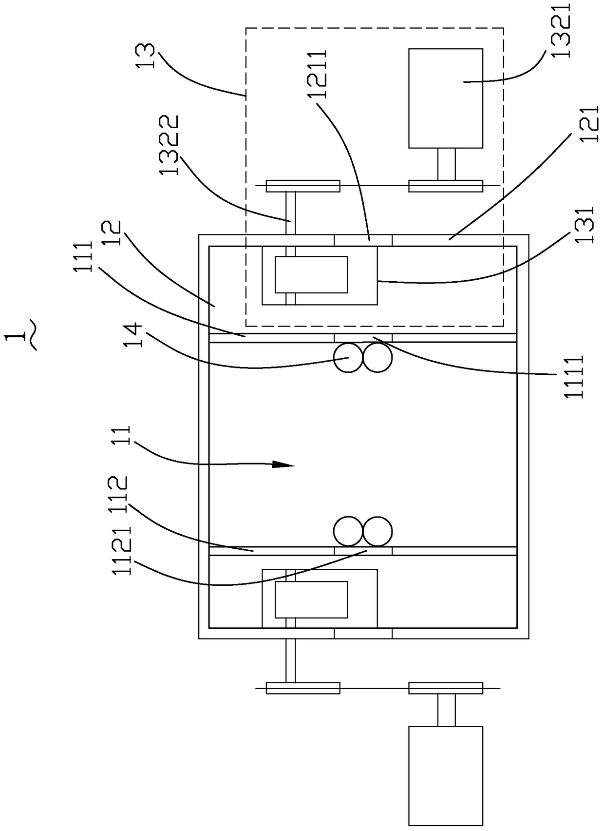
[0019] refer to figure 1 , figure 1 It is a structural schematic diagram of the electroplating copper tank device of the present invention. The copper electroplating tank device 1 includes a main tank 11 , two auxiliary tanks 12 , two liquid blocking mechanisms 13 and a squeezing roller 14 . The two auxiliary tanks 12 extend from both ends of the main tank 11, the squeeze rollers 14 are located at both ends of the main tank 11 and inside the main tank 11, and the liquid blocking mechanism 13 is respectively Cooperate with the auxiliary tank 12.

[0020] The main tank 11 includes a feed side wall 111 and a discharge side wall 112 oppositely arranged, the feed side wall 111 includes a feed channel 1111, the discharge side wall 112 includes a discharge channel 1121, and the feed side wall 111 includes a feed channel 1121. The material channel 1111 is o...


PUM

PropertyMeasurementUnit
lengthaaaaaaaaaa

Abstract

The invention discloses a copper tank electroplating device. The device comprises a main tank, two auxiliary tanks and two liquid blocking mechanisms. The main tank comprises a feeding side wall and a discharging side wall which are oppositely arranged, and the feeding side wall comprises a feeding channel; the discharging side wall comprises a discharging channel; the two auxiliary tanks extend from the feeding side wall and the discharging side wall respectively, and each auxiliary tank comprises a gateway right opposite to the feeding channel and the discharging channel; the two auxiliary tanks are each provided with one liquid blocking mechanism in a matched manner, and each liquid blocking mechanism comprises a liquid blocking plate and a driving device; the liquid blocking plates are arranged in the auxiliary tanks respectively, and each driving device drives the corresponding liquid blocking plate to do back-and-forth movement in the width direction of the copper tank electroplating device; and electroplating liquid in the electroplated copper tank enables the liquid blocking plates to cover the gateway to achieve liquid blocking. The copper tank electroplating device is simple in structure and good in liquid blocking effect, and the height and the width of the whole device are not increased.

Description

technical field [0001] The invention relates to the technical field of electroplating equipment, in particular to an electroplating copper tank device. Background technique [0002] Printed circuit boards are developing towards thinner, finer and thinner circuits. In order to make finer circuits, circuit boards have higher requirements on the uniformity of surface copper thickness. The application of vertical electroplating lines can well solve the problem of electroplating uniformity; at the same time , in order to improve production efficiency, continuous electroplating equipment has gradually replaced traditional batch electroplating equipment. As a result, vertical continuous electroplating equipment was proposed and widely used in the production process of printed circuit boards. [0003] In the related technology of vertical continuous electroplating, the inlet and outlet of the electroplating copper tank are completely open. When the entire electroplating production ...

Claims


Application Information

Patent Timeline
Patent Type & Authority Patents(China)
IPC IPC(8): C25D17/02C25D3/38
Inventor 赵喜华甘林肖昭荣蔡志浩
Owner DONGGUAN WERY DOOD CIRCUIT BOARD EQUIP
Why Eureka
Try Eureka