Stilling well for connecting vertical shaft with recession tunnel

A stilling well and water receding technology, which is applied in water conservancy projects, sea area projects, coastline protection, etc., can solve the problems of strong splashing and ejection of water flow, and achieve the effects of reducing momentum exchange, reducing height, and ensuring safety

Active Publication Date: 2016-01-06
POWERCHINA ZHONGNAN ENG
View PDF4 Cites 2 Cited by
  • Summary
  • Abstract
  • Description
  • Claims
  • Application Information

AI Technical Summary

Problems solved by technology

[0005] From the analysis of the movement trajectory of the water flow in the stilling well, since the wall of the cylindrical stilling well has a rigid lateral constraint on the water flow, the inflow and outflow of the water flow occur at the same spatial position, and t

Method used


Image

  • Stilling well for connecting vertical shaft with recession tunnel
  • Stilling well for connecting vertical shaft with recession tunnel
  • Stilling well for connecting vertical shaft with recession tunnel

Examples


Embodiment 1

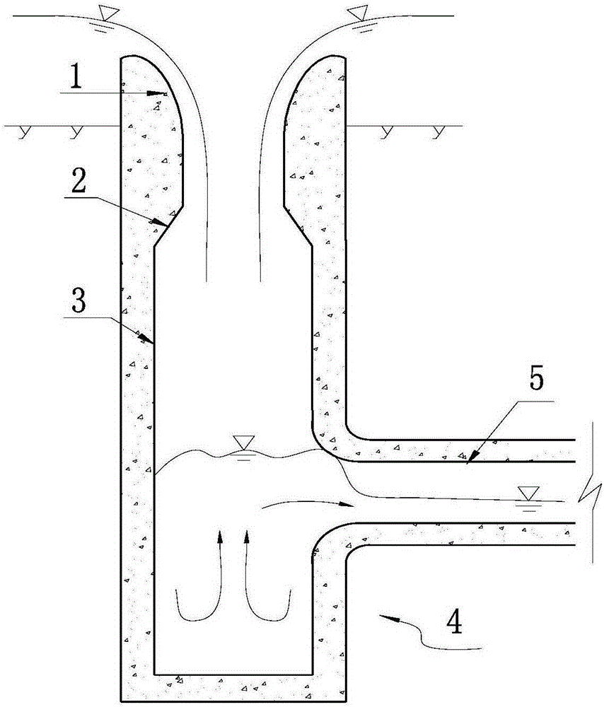
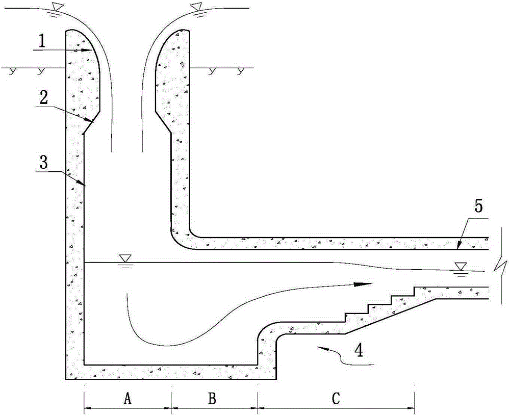
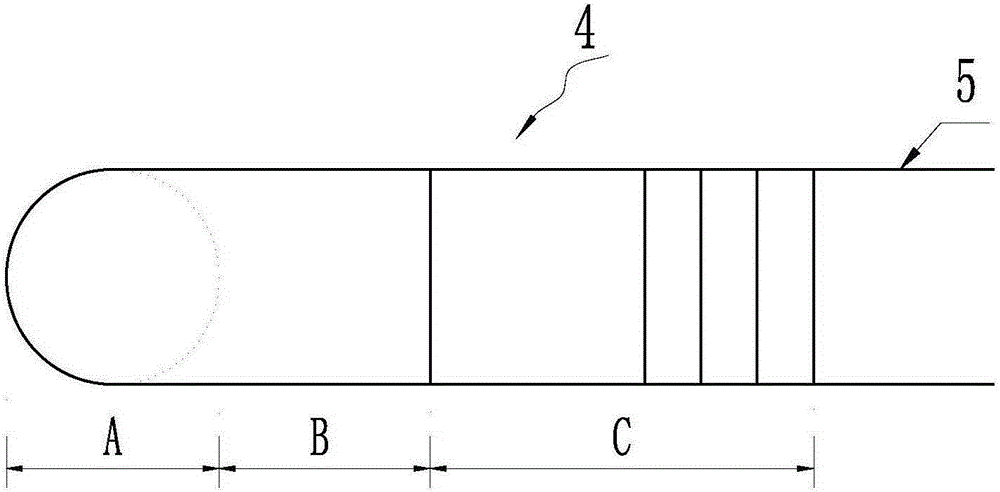
[0028] Such as figure 2 , image 3 As shown, the stilling well 4 is included in this embodiment, the water inlet end of the stilling well 4 is connected to the water outlet end of the shaft 3, and the water inlet end of the shaft 3 is connected to the bottom of the overflow weir 1 through the transition section 2, The stilling well 4 is provided with a splashing section A, a buffer section B and an adjusting section C, which are connected in sequence, and the bottom plate elevation of the stilling well adjusting section C is higher than that of the buffer section B , a step is formed on the vertical plane, the first half of the adjustment section C is a horizontal plane, the second half is a ladder type, and the end is connected with the retreating tunnel 5 .

[0029] Such as Figure 4 with Figure 5 As shown, when the width of the stilling well 4 is inconsistent with the width of the water retreat tunnel 5, the adjustment section C is connected with the water retreat tunn...

Embodiment 2

[0032] Such as Image 6 As shown, the adjusting section C of the stilling well in this embodiment has a stepped slope structure as a whole, and the rest of the structure is similar to that of Embodiment 1, and will not be repeated here.

Embodiment 3

[0034] Such as Figure 7 As shown, the adjusting section C of the stilling well in this embodiment has a slope structure as a whole, and the rest of the structure is similar to that of Embodiment 1, and will not be repeated here.


PUM


Abstract

The invention discloses a stilling well for connecting a vertical shaft with a recession tunnel. The stilling well comprises a stilling well body. The water inlet end of the stilling well body is communicated with the water outlet end of the vertical shaft. The water outlet end of the stilling well body is communicated with the water inlet end of the recession tunnel. A splashing section, a buffering section and an adjusting section which are sequentially connected are arranged in the stilling well body. The water inlet end of the splashing section is communicated with the water outlet end of the vertical shaft. The water outlet end of the adjusting section is communicated with the water inlet end of the recession tunnel. The bottom plate elevation of the water inlet end of the adjusting section is not lower than the bottom plate elevations of the splashing section and the buffering section. The bottom plate elevation of the water outlet end of the adjusting section is higher than the bottom plate elevations of the splashing section and the buffering section. The adjusting section is of a reverse slope structure with the water outlet end higher than the water inlet end. By means of the stilling well, splashed and ejected water bodies can be prevented from hitting the top of the recession tunnel, safety of concrete structures is ensured, the requirement for the discharge capacity of the recession tunnel is met to the maximum extent, and meanwhile the water flow state in the recession tunnel is stable and smooth.

Description

technical field [0001] The invention relates to the field of flood discharge and energy dissipation for shaft spillways in water conservancy and hydropower projects, in particular to a stilling shaft connecting shafts and water retreat tunnels. Background technique [0002] Shaft spillways are used for flood discharge and energy dissipation in water conservancy and hydropower projects, such as figure 1 As shown, its main components are: overflow weir 1, transition section 2, vertical shaft 3, stilling shaft 4, and water retreat tunnel 5. The water retreat tunnel is connected with the stilling well 4. [0003] The water flow in the shaft spillway passes through the overflow weir and forms a high-speed water flow at the lower end of the overflow weir curve; the high-speed water flow breaks away from the shaft wall at the transition section and falls freely in the shaft cavity, shearing and entraining with the air during the falling process The effect, carrying a large amount...

Claims


Application Information

Patent Timeline
IPC IPC(8): E02B8/06
Inventor 戴晓兵周琦苗宝广
Owner POWERCHINA ZHONGNAN ENG
Why Eureka
Try Eureka