Pneumatic GM refrigerating machine and control process thereof
A technology for controlling processes and refrigerators, applied in refrigerators, refrigeration components, refrigeration and liquefaction, etc., can solve the problems of high-pressure gas consumption, low theoretical efficiency, low efficiency, etc., to improve efficiency, improve refrigeration efficiency, and easy to operate. Effect
- Summary
- Abstract
- Description
- Claims
- Application Information
AI Technical Summary
Problems solved by technology
Method used
Image

Examples
Embodiment 1
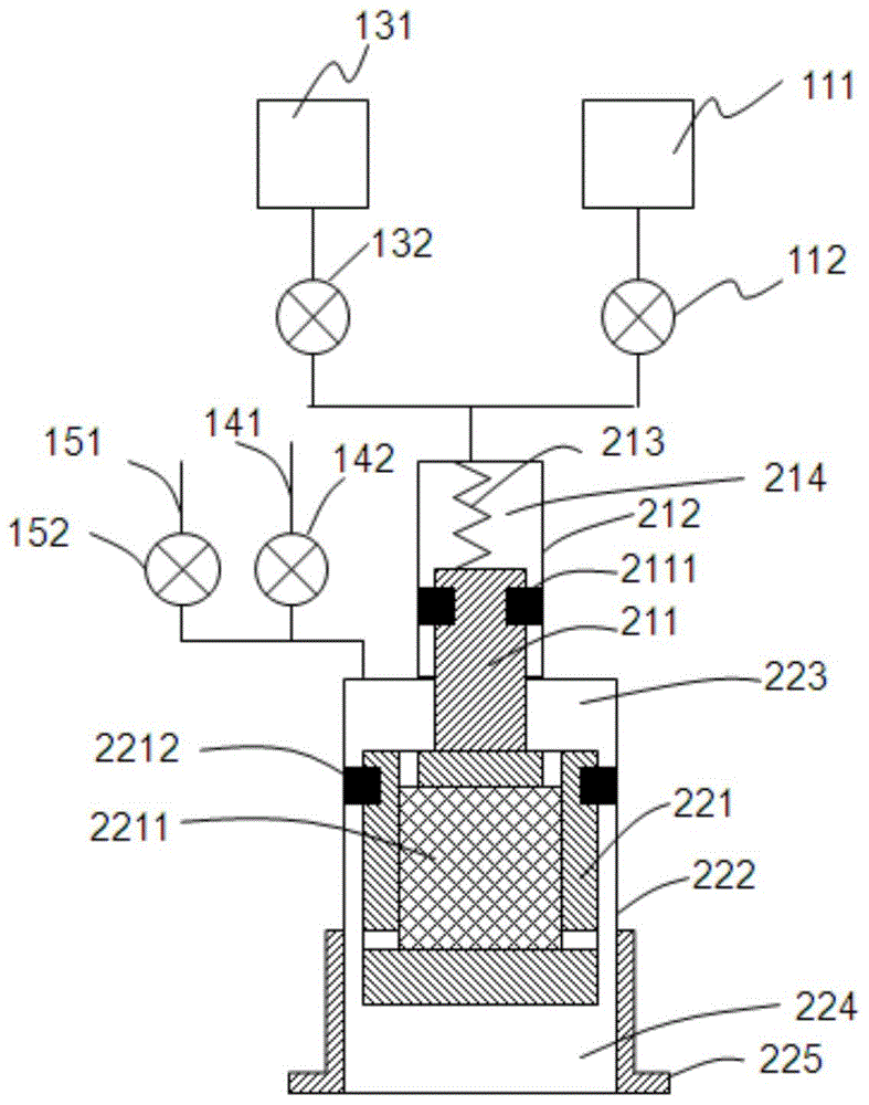
[0041] A pneumatic GM refrigerator is a single-stage pneumatic GM refrigerator with two gas storages, and the structure is as follows figure 1 As shown, it includes a drive cylinder 212, a refrigeration cylinder 222, a drive piston 211, a push piston 221 and a cooling heat exchanger 225, the drive cylinder 212 is connected up and down with the refrigeration cylinder 222, the drive piston 211 is connected up and down with the push piston 221, and the drive piston 211 is slidingly connected with the drive cylinder 212, the drive piston 211 can slide in the drive cylinder 212, the drive chamber 214 is formed between the drive cylinder 212 and the drive piston 211, the push piston 221 can slide in the refrigeration cylinder 222, and the push piston 221 and the refrigeration The cylinder 222 is slidingly connected, and the interior of the refrigeration cylinder 222 is divided into a room temperature cavity 223 and a low temperature cavity 224 by the push piston 221. The cooling heat...
Embodiment 2
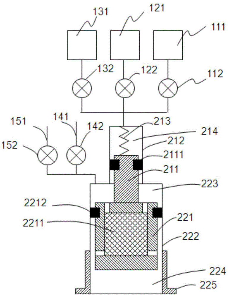
[0051] A pneumatic GM refrigerator is a single-stage pneumatic GM refrigerator with three gas storages, the structure of which is as follows figure 2 As shown, the difference with the structure of the single-stage pneumatic GM refrigerator with two gas storages in Embodiment 1 is that the driving cavity 214 is connected with the low-pressure gas storage 111, the medium-pressure gas storage 121 and the high-pressure gas storage 131 at the same time, and the driving cavity 214 is connected with the high-pressure gas storage 131. The connecting pipelines of the low-pressure gas storage 111 , the medium-pressure gas storage 121 and the high-pressure gas storage 131 are respectively provided with a low-pressure gas storage valve 112 , a medium-pressure gas storage valve 122 and a high-pressure gas storage valve 132 .
[0052] In this embodiment, the driving piston 211 is integrally connected with the pushing piston 221 .
[0053] The working process of the pneumatic GM refrigerato...
Embodiment 3
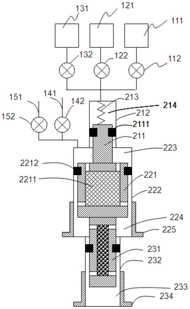
[0063] A pneumatic GM refrigerator is a two-stage pneumatic GM refrigerator with three gas storages, the structure of which is as follows image 3 As shown, the difference with the structure of the three-gas storage single-stage pneumatic GM refrigerator in Embodiment 2 is that: the refrigeration cylinder 222 is connected with the second-stage cylinder 232, the push piston 221 is connected with the second-stage push piston 231, and the second The first-stage push piston 231 is slidingly connected with the second-stage cylinder 232, and the second-stage low-temperature cavity 233 is formed between the second-stage push piston 231 and the second-stage cylinder 232, and the bottom end of the second-stage cylinder 232 is connected to the second-stage cooling exchange. Heater 234.
[0064]According to actual needs, also can continue to be provided with the third-stage moving piston and the third-stage cylinder on the second-stage moving piston 231 and the second-stage cylinder 232,...
PUM
 Abstract
Description
Claims
Application Information
 - R&D
- Intellectual Property
- Life Sciences
- Materials
- Tech Scout
- Unparalleled Data Quality
- Higher Quality Content
- 60% Fewer Hallucinations
Browse by: Latest US Patents, China's latest patents, Technical Efficacy Thesaurus, Application Domain, Technology Topic, Popular Technical Reports.
© 2025 PatSnap. All rights reserved.Legal|Privacy policy|Modern Slavery Act Transparency Statement|Sitemap|About US| Contact US: help@patsnap.com