
Microscope locating, tracking and imaging method and apparatus, and urinary sediment analysis system

A technology of positioning tracking and imaging methods, which is applied in microscopes, analytical materials, optics, etc., can solve the problems of taking a long time, affecting the sample inspection rate, and being unable to determine the target particle statistics, so as to ensure accuracy and save photos. the effect of time

Active Publication Date: 2016-01-06
SUZHOU MINDRAY SCI CO LTD
View PDF4 Cites 11 Cited by
  • Summary
  • Abstract
  • Description
  • Claims
  • Application Information

AI Technical Summary

Problems solved by technology

However, there are shortcomings in this method. Since images need to be collected for all areas, the sample inspection process will take a long time. Usually, the process of taking pictures of a sample will take tens of minutes, which will affect the sample inspection rate.
[0004] In the existing technology, another way to collect images through a high-magnification lens is to randomly select a fixed number of images from the area containing the target particles to follow up and take pictures. This way of collecting images can save time. However, this method has disadvantages. Since the photo path is randomly selected from the area containing the target particles, it is impossible to determine that the selection of the target particles has reached the maximum statistic, which will have a certain adverse effect on the accuracy of the sample results.

Method used


Image

  • Microscope locating, tracking and imaging method and apparatus, and urinary sediment analysis system
  • Microscope locating, tracking and imaging method and apparatus, and urinary sediment analysis system
  • Microscope locating, tracking and imaging method and apparatus, and urinary sediment analysis system

Examples


Embodiment Construction

[0046] In order to make the object, technical solution and advantages of the present invention more clear, the present invention will be further described in detail below in conjunction with the accompanying drawings and embodiments. It should be understood that the specific embodiments described here are only used to explain the present invention, not to limit the present invention.

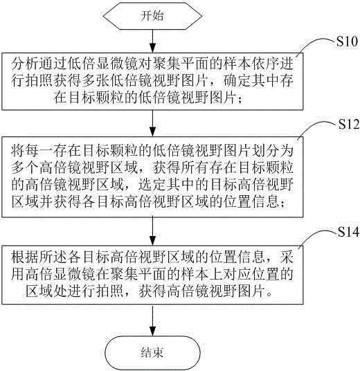
[0047] Such as figure 1 As shown in FIG. 1 , the main flow chart of an embodiment of a microscope positioning tracking imaging method provided by the present invention is shown. In this embodiment, the method includes the steps of:

[0048] Step S10, analyzing and taking pictures of the samples of the aggregation plane through a low-magnification lens in order to obtain multiple low-magnification lens field of view pictures, and determining the low-magnification lens field of view pictures in which the target particles exist;

[0049]It can be understood that the analysis is generally implemen...


PUM


Abstract

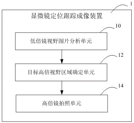
Embodiments in the invention disclose a microscope locating, tracking and imaging method. The method comprises the following steps: analyzing a plurality of low-power field pictures obtained by sequentially shooting samples of aggregation planes with a low-power lens and determining low-power field pictures in which target particles exist; dividing each low-power field picture in which the target particles exist into a plurality of high-power field areas, acquiring all the high-power field areas where the target particles exist, selecting target high-power field areas therein and acquiring positional information of each target high-power field area; and shooting areas at corresponding positions on the samples of aggregation planes with a high-power lens according to the positional information of each target high-power field area so as to obtain high-power field pictures. The embodiments in the invention also disclose a microscope locating, tracking and imaging apparatus. Through implementation of the embodiments in the invention, a sample detection speed can be increased, and accuracy of sample examination results can be guarantee as much as possible.

Description

technical field [0001] The invention relates to the technical field of in vitro diagnosis, in particular to a microscope positioning tracking imaging method, device and urine sediment analysis system. Background technique [0002] Microscope systems are widely used in in vitro diagnostic instruments (such as automatic urine sediment analysis systems) to collect images of sample particles on the focal plane within the counting range, and use a low-power microscope (hereinafter referred to as low-power lens) to locate the target particles, and then in the The target particles are tracked and photographed under a high-power microscope (hereinafter referred to as high-power microscope). [0003] In the existing technology, one way of collecting images through a high-power lens is to track and take pictures of all regions containing target particles. However, there are shortcomings in this method. Since images need to be collected for all areas, the sample inspection process wil...

Claims


Application Information

Patent Timeline
Patent Type & Authority Applications(China)
IPC IPC(8): G01N15/00G02B21/36
Inventor 何延峰徐俊王迪
Owner SUZHOU MINDRAY SCI CO LTD
Learn More