Audio output control method, control system and electronic equipment

A technology of audio output and control method, which is applied in the electronic field, and can solve problems such as loud and small voices, inability to communicate normally, and inability to see and hear normally, so as to achieve the effect of normal communication

Active Publication Date: 2016-01-06
FUZHOU ROCKCHIP SEMICON
View PDF6 Cites 3 Cited by
  • Summary
  • Abstract
  • Description
  • Claims
  • Application Information

AI Technical Summary

Problems solved by technology

[0004] In view of the above-mentioned shortcomings of the prior art, the purpose of the present invention is to provide an audio output control method, control system and electronic equipment, which are used to solve the problem of inability to listen and listen normally whe

Method used


Image

  • Audio output control method, control system and electronic equipment
  • Audio output control method, control system and electronic equipment
  • Audio output control method, control system and electronic equipment

Examples


Embodiment 1

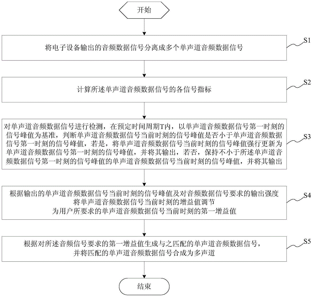
[0057] This embodiment provides an audio output control method, the control method is applied to electronic equipment, please refer to figure 1 , which is a schematic flow chart of the audio output control method. Such as figure 1 As shown, the audio output control method includes the following steps:

[0058] S1. Separate the audio data signal output by the electronic device into multiple monophonic audio data signals. In this embodiment, according to the data flow mode of the audio data signal, the audio data signal output by the electronic device is divided into X(n) into multiple monophonic audio data signals, that is, X 1 (n), X 2 (n),...,X L (n),...,X M (n).

[0059] S2. Calculate each signal index of the monophonic audio data signal. In this step, numerical values ​​are exchanged between different indicators of each monophonic audio data signal, and the signal indicators include amplitude, energy, intensity, and the like. The calculation formulas of each signal ...

Embodiment 2

[0087] This embodiment provides an audio output control system 1, which is applied to electronic equipment. see Figure 5 , is shown as a schematic diagram of the principle structure of the control system with audio output. Such as Figure 5 As shown, the audio output control system includes: parameter preset module 11, channel separation module 12, calculation module 13, detection module 14, update module 15, output module 16, maintenance module 17, gain adjustment module 18, and audio processing module 19. Wherein, the detection module 14 includes a speech detection unit 141 and a peak detection unit 142 . The audio processing module 19 includes an output signal calculation unit 192 and a multi-channel summing unit 193 .

[0088] The parameter preset module 11 is used to inform the data flow characteristics of the audio data signal output by the electronic device and the output intensity X of the monophonic audio data signal required by the user req . Wherein, the data...


PUM


Abstract

The invention provides an audio output control method. The audio output control method comprises: dividing an audio data signal into multiple single-track audio data signals, judging whether a signal peak value of the single-track audio data signals at the current moment is less than that of the single-track audio data signals at a first moment, if yes, updating the signal peak value of the single-track audio data signals at the current moment into the signal peak value of the single-track audio data signals at the first moment, otherwise, keeping the signal peak value of the single-track audio data signals at the current moment not less than that of the single-track audio data signals at the first moment; regulating gain values of the single-track audio data signals at the current moment as first gain values, which are required by users, of the single-track audio data signals at the current moment; generating matching single-track audio data signals and combining a multi-track audio data signal. By means of the audio output control method, control system and electronic equipment provided by the invention, video player can ensure normal vision and audio, a phenomenon that sounds are suddenly loud or small will not occur, and normal communication between the users is ensured.

Description

technical field [0001] The invention belongs to the field of electronic technology, and relates to a control method and system, in particular to an audio output control method, control system and electronic equipment. Background technique [0002] At present, consumer electronics products are updated very quickly. Many products are pursuing low hardware costs and achieving good functional effects, such as tablets, walkie-talkies, and remote visual dialogues. These product forms have entered the low-profit living space. Each manufacturer is reducing the cost of hardware, one of the important links is to reduce the cost of the audio output module Codec, and even many manufacturers directly use the audio output module with only DA (digital to analog module) to achieve playback . This kind of hardware will not process the audio digital signal ready to be output, then we will encounter many scenarios, such as the digital gain value of the audio track itself of a certain film sou...

Claims


Application Information

Patent Timeline
IPC IPC(8): G06F3/16
Inventor 陈长海
Owner FUZHOU ROCKCHIP SEMICON
Why Eureka
Try Eureka