Magnetic gap channel pass-type demagnetizer

A magnetic gap and demagnetization technology, which is applied in the direction of magnetic objects, electrical components, circuits, etc., can solve the problems of excessive residual magnetism, dirty demagnetization of bearing rings, reduced processing accuracy and product quality, and achieves the improvement of demagnetization pass rate, The demagnetization effect is stable and the effect of reducing the residual magnetism of the workpiece

Inactive Publication Date: 2016-01-06
LUOYANG BEARING SCI & TECH CO LTD
View PDF6 Cites 4 Cited by
  • Summary
  • Abstract
  • Description
  • Claims
  • Application Information

AI Technical Summary

Problems solved by technology

For bearing products with strict requirements on residual magnetism, the demagnetization of the bearing ring is not clean, and the residual magnetism exceeds the standard, which will reduce its processing accuracy and product quality

Method used


Image

  • Magnetic gap channel pass-type demagnetizer
  • Magnetic gap channel pass-type demagnetizer

Examples


Embodiment Construction

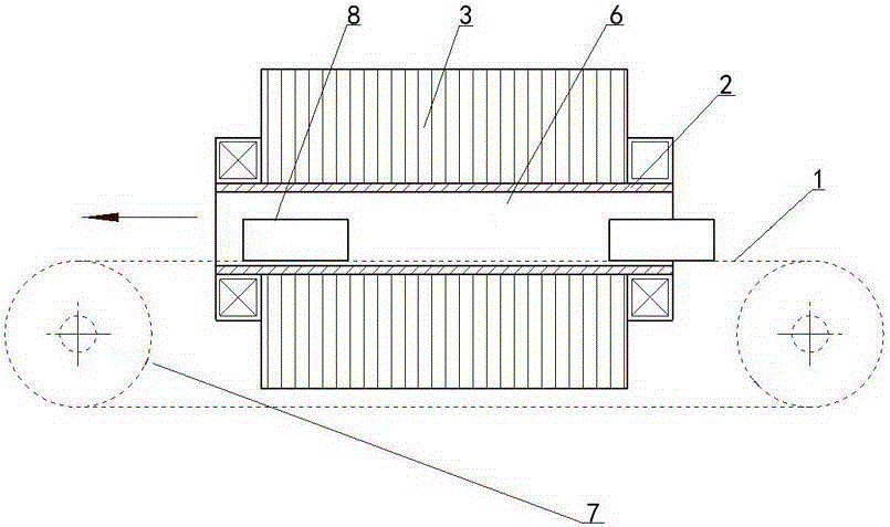
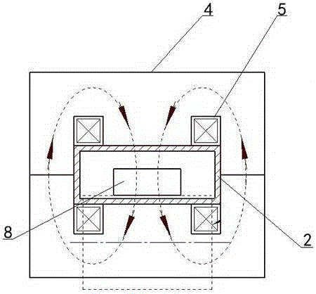
[0013] As shown in the figure: a magnetic gap channel pass-through demagnetization device, including a belt conveyor 1, a magnetic gap channel frame 2 and a demagnetization assembly 3, the belt conveyor 1 is used to transport the workpiece 8 to be demagnetized, and the magnetic gap channel frame 2 The material is bakelite board or phenolic board. The demagnetization assembly 3 includes two "E" shaped iron cores 4 and coil windings 5 ​​matched with the iron cores 4. The "E" shaped iron core 4 has three iron core columns located in the middle The iron core column is shorter than the iron core column at both ends, and the coil winding 5 is sleeved on the iron core column in the middle, and the coil winding 5 is connected to the demagnetization circuit, and the openings of the two "E" shaped iron cores 4 are opposite to each other. After the docking, a magnetic gap channel 6 is formed, and the magnetic gap channel frame 2 is penetrated in the magnetic gap channel 6, and the upper e...


PUM


Abstract

The invention relates to a magnetic gap channel pass-type demagnetizer, comprising a belt conveyer, a magnetic gap channel frame, and a demagnetization assembly. The demagnetization assembly comprises two E-shaped iron cores and coil windings matched with the iron cores. The E-shaped iron core is provided with three iron core columns, and the iron core column on the middle is shorter than the iron core columns on two ends. A coil winding is sleeved on the iron core column on the middle. The coil windings are connected with a demagnetization circuit. After openings of the two E-shaped iron cores are joined oppositely, a magnetic gap channel is formed. The magnetic gap channel frame passes through the magnetic gap channel. The conveyer belt on the upper end of the belt conveyer is arranged passing through the magnetic gap channel frame. Two guiding wheels of the belt conveyer are respectively arranged on two ends of the magnetic gap channel frame. The conveyer belt on the upper end of the belt conveyer is supported by the magnetic gap channel frame. The magnetic gap channel pass-type demagnetizer can improve magnetic field intensity of a magnetic field, and effectively improve demagnetization quality of workpiece, and reduce energy consumption, and improve processing precision of products.

Description

technical field [0001] The invention relates to the technical field of demagnetization treatment devices, in particular to a magnetic gap passage-passing type demagnetization device. Background technique [0002] In industrial production, many workpieces are processed by using electromagnetic chucks to absorb workpieces. After processing, the magnetism needs to be eliminated to ensure the processing accuracy and inspection quality of the products. However, for the demagnetization of mass-produced workpieces with multiple varieties, different shapes, and large size differences, a demagnetization device with strong compatibility with workpiece sizes and suitable for multiple varieties and specifications is needed to achieve the purpose of demagnetizing batch workpieces. [0003] At present, many machining factories use pass-through demagnetization machines, most of which adopt the gantry frame structure, which is directly surrounded by coils to form a square frame, and the con...

Claims


Application Information

Patent Timeline
Patent Type & Authority Applications(China)
IPC IPC(8): H01F13/00
Inventor 李洛李昊谦高雯
Owner LUOYANG BEARING SCI & TECH CO LTD
Why Eureka
Try Eureka