
A helium-doped modified lithium iron phosphate thin film positive electrode material and preparation method thereof

A thin-film cathode, lithium iron phosphate technology, applied in chemical instruments and methods, phosphorus compounds, battery electrodes, etc., can solve the problems of limited improvement in electrochemical properties of materials, small size influence, and many processes, and shorten the preparation time. , The effect of improving productivity and high conductivity

Inactive Publication Date: 2018-08-17
SICHUAN UNIV
View PDF8 Cites 0 Cited by
  • Summary
  • Abstract
  • Description
  • Claims
  • Application Information

AI Technical Summary

Problems solved by technology

However, there are still deficiencies in this type of modification method: First, although the doping of transition group elements can improve the bulk electronic conductivity of the material, it has little effect on the size of the material, and it is not easy to increase the lithium ion diffusion rate of the material, so it is difficult for The improvement of the electrochemical performance of the material is limited; second, LiFePO 4 The metal ion doping of positive electrode materials often involves basic processes such as batching, mixing (ball milling), heat treatment, and sintering. Among them, only mixing takes 12 to 24 hours, and sintering takes 4 to 6 hours. Longer time reduces the production efficiency of positive electrode materials; third, due to the high cost of some metal cations and the need for long-term high-temperature sintering in an inert gas atmosphere, LiFePO is virtually increased. 4 Preparation cost of cathode material

Method used


Image

  • A helium-doped modified lithium iron phosphate thin film positive electrode material and preparation method thereof
  • A helium-doped modified lithium iron phosphate thin film positive electrode material and preparation method thereof
  • A helium-doped modified lithium iron phosphate thin film positive electrode material and preparation method thereof

Examples


Embodiment 1

[0030] (1) Place the cleaned 316 stainless steel sheet in a magnetron sputtering vacuum chamber with a background vacuum pressure of 9.0×10 -4 Pa, under the sputtering power of 40W, carry out radio frequency magnetron sputtering coating, with a purity of not less than 99.95wt% ceramic LiFePO 4 The target is used as a sputtering source, and a mixed gas of Ar and He is introduced at the same time during sputtering, wherein the pressure of Ar is 0.8Pa, the gas pressure ratio of Ar and He is 10:1, and the sputtering deposition time is 20min;

[0031] (2) LiFePO obtained in step (1) 4 / He thin film cathode material was annealed in a high vacuum annealing furnace, the annealing temperature was 300°C, and the annealing pressure was 9.0×10 -4 Pa, annealed for 1 hour, after the annealing is completed, cool with the furnace and come out of the furnace.

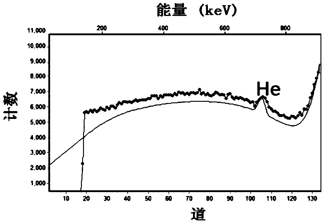
[0032] It is measured that the content of He atoms in the positive electrode material thin film is 8.2 at%, the discharge capacity o...

Embodiment 2

[0034] (1) Place the cleaned 316 stainless steel sheet in a magnetron sputtering vacuum chamber with a background vacuum pressure of 7.0×10 -4 Pa, under the sputtering power of 60W, carry out radio frequency magnetron sputtering coating, with a purity of not less than 99.95wt% ceramic LiFePO 4 The target is used as the sputtering source, and a mixed gas of Ar and He is introduced at the same time during sputtering, wherein the pressure of Ar is 1.0Pa, the gas pressure ratio of Ar and He is 10:4, and the sputtering deposition time is 40min;

[0035] (2) LiFePO obtained in step (1) 4 / He thin film cathode material was annealed in a high vacuum annealing furnace, the annealing temperature was 600°C, and the annealing pressure was 7.0×10 -4 Pa, annealed for 1.5 hours, after the annealing is completed, cool with the furnace and come out of the furnace.

[0036] The content of He atoms in the film prepared in this embodiment is 22.0 at%. and the helium-doped LiFePO 4 Cathode mat...

Embodiment 3

[0038] (1) Place the cleaned 316 stainless steel sheet in a magnetron sputtering vacuum chamber with a background vacuum pressure of 8.0×10 -4 Pa, under the sputtering power of 60W, carry out radio frequency magnetron sputtering coating, with a purity of not less than 99.95wt% ceramic LiFePO 4 The target is used as the sputtering source, and a mixed gas of Ar and He is introduced at the same time during sputtering, wherein the pressure of Ar is 2.0Pa, the gas pressure ratio of Ar and He is 10:2, and the sputtering deposition time is 20min;

[0039] (2) LiFePO obtained in step (1) 4 / He thin film cathode material is annealed in a high vacuum annealing furnace, the annealing temperature is 400°C, and the annealing pressure is 8.0×10 -4 Pa, annealed for 1.2 hours, after the annealing is completed, cool with the furnace and come out of the furnace.

[0040] It is measured that the content of He atoms in the positive electrode material thin film is 13.5 at%, the discharge capacit...


PUM


Abstract

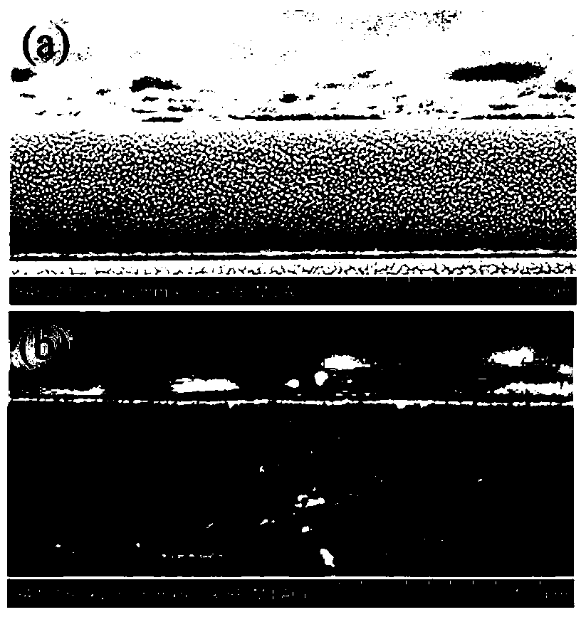
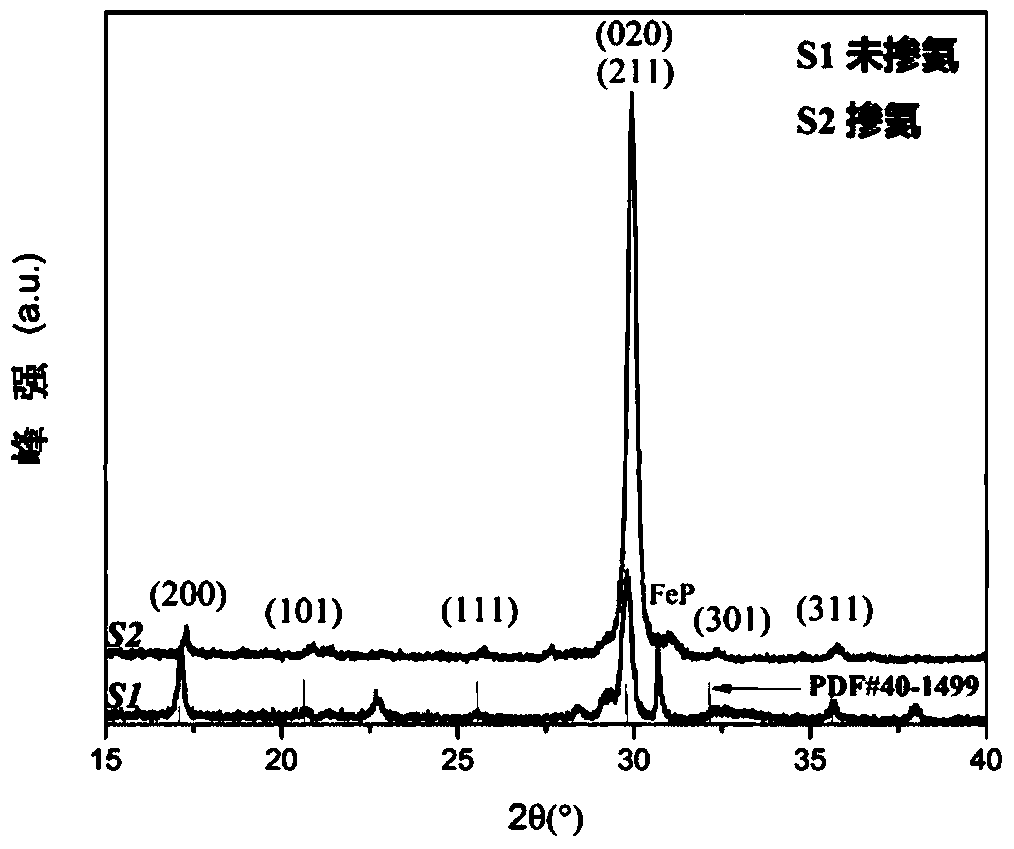
The invention discloses a preparation method of a helium-doped modified lithium iron phosphate thin-film positive electrode material. The method comprises the following steps: plating a current collector of a positive plate with a LiFePO<4> thin film through a magnetron sputtering method, and introducing He gas at the same time to dope He into the LiFePO<4> thin film; and performing high-vacuum annealing on an obtained LiFePO<4> / He thin-film positive electrode material in a conventional way, wherein the prepared thin film has a porous structure and a b-axis crystallization preferred orientation characteristic, and the content of He atoms is 8-34 atom percent. A discharge capacity of a button type lithium ion battery assembled with the positive electrode material is 84-141mAh / g at a 0.1C test rate, and an electric capacity attenuation rate of 50 cycles is 14.2-24.0 percent. The prepared thin-film LiFePO<4> positive electrode material has a higher electric conductivity and shorter ion and electron transport paths, thereby improving the discharge capacity, rate performance and cycle performance of the lithium battery, and greatly improving an electrochemical performance of the material. Moreover, a process is simple, mature and easy to grasp and control.

Description

technical field [0001] The invention belongs to the technical field of thin-film cathode materials in lithium ion batteries and their preparation, and in particular relates to a helium-doped modified lithium iron phosphate thin-film cathode material and a preparation method thereof. Background technique [0002] As a new type of chemical power source, lithium-ion batteries have become a hot spot in the field of new energy materials due to their advantages such as high output voltage, high specific energy, long cycle life, small self-discharge, safety, no memory effect, and environmental friendliness. [0003] For thin-film lithium batteries, the cathode material is a key factor affecting the performance of lithium-ion batteries. Currently, the commonly used cathode materials for thin-film lithium-ion batteries include LiCoO 2 , LiMn 2 o 4 、LiFePO 4 Wait. Among them, LiFePO 4 Because of its advantages such as low cost, non-toxicity, long cycle life, and good thermal sta...

Claims


Application Information

Patent Timeline
Patent Type & Authority Patents(China)
IPC IPC(8): H01M4/58H01M10/0525C01B25/45
CPCC01B25/45H01M4/5825H01M10/0525Y02E60/10
Inventor 劳远侠汪渊石云龙王茂
Owner SICHUAN UNIV
Learn More