
Fuel cell system and control method thereof

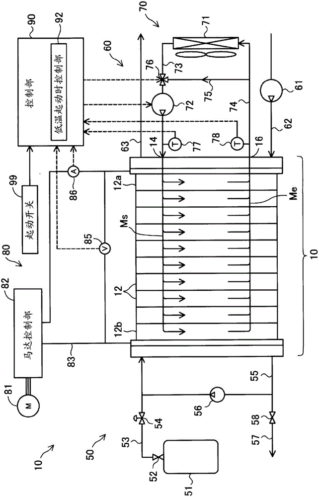
A fuel cell system and fuel cell technology, applied in the direction of fuel cells, circuits, electrical components, etc., can solve the problems of inability to raise the overall temperature of the fuel cell stack, slow temperature rise, etc.

Active Publication Date: 2016-10-19
TOYOTA JIDOSHA KK
View PDF4 Cites 0 Cited by
  • Summary
  • Abstract
  • Description
  • Claims
  • Application Information

AI Technical Summary

Problems solved by technology

[0004] However, according to the above-mentioned prior art, if the circulation of cooling water continues to be stopped, there will be a portion where the temperature rises slowly in the stacking direction of the fuel cell stack, and there is a problem that the temperature of the entire fuel cell stack cannot be uniformly raised.

Method used


Image

  • Fuel cell system and control method thereof
  • Fuel cell system and control method thereof

Examples


Deformed example 1

[0053] In the above-described embodiment and its modification, the heat generation value of the fuel cell stack 10 is obtained based on the output voltage Vfc and the output current Ifc of the fuel cell stack 10, and the fuel cell stack 10 is estimated based on the heat generation value and the heat capacity of the fuel cell stack 10. The structure of the internal temperature T3, but not limited to this. For example, a temperature sensor may be used to obtain the temperature of a representative fuel cell unit (for example, a central unit in the stacking direction) constituting the fuel cell stack 10, and obtain the obtained temperature as an internal temperature. In addition, the temperature distribution of each fuel cell unit may be obtained experimentally in advance, and the temperature distribution of a representative fuel cell unit (for example, a unit in the center in the stacking direction) constituting the fuel cell stack 10 may be obtained using a temperature sensor. t...

Deformed example 2

[0055] In the above embodiment and its modifications, the fuel cell system mounted on a vehicle has been described as an example, but the present invention is not limited thereto and can be applied to various mobile bodies such as motorcycles, ships, airplanes, and robots. In addition, the present invention is not limited to a fuel cell system mounted on a mobile body, and may be applied to a stationary fuel cell system or a portable fuel cell system.

Deformed example 3

[0057] In the above-mentioned embodiment and its modifications, the solid polymer fuel cell is used in the fuel cell stack, but various fuel cells such as phosphoric acid fuel cells, molten carbonate fuel cells, and solid oxide fuel cells may also be used. The invention is applied to batteries.


PUM


Abstract

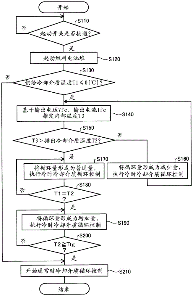
A fuel cell system comprises a fuel cell stack, a circulation flow path of a cooling medium, a pump provided in the circulation flow path, a supply-side temperature sensor provided to detect a supplied cooling medium temperature, a discharge-side temperature sensor provided to detect a discharged cooling medium temperature, and a cold-start controller configured to control a circulation volume of the cooling medium by the pump at a cold start of the fuel cell stack. The cold-start controller estimates a fuel cell internal temperature and selectively sets the circulation volume of the cooling medium between a reduced volume and a normal volume, based on a magnitude relationship between the internal temperature and the discharged cooling medium temperature. When the supplied cooling medium temperature becomes equal to the discharge cooling medium temperature after setting the circulation volume, the cold-start controller sets the circulation volume of the cooling medium to an increased volume (maximum circulation volume).

Description

technical field [0001] The present invention relates to a fuel cell system including a fuel cell stack and a control method for the fuel cell system. Background technique [0002] Conventionally, in a fuel cell system, when starting a fuel cell stack, when the internal temperature of the fuel cell is below 0° C., a technique has been proposed in which the pump of the cooling water is stopped to stop the circulation of the cooling water (e.g. , refer to Patent Document 1). According to this technology, it is possible to increase the calorific value after starting below the freezing point, and to increase the temperature increase rate of the fuel cell stack to shorten the start-up time. [0003] Patent Document 1: Japanese Patent Laid-Open No. 2010-186599 [0004] However, according to the aforementioned prior art, if the circulation of the cooling water continues to be stopped, there will be a portion in which the temperature rises slowly in the stacking direction of the fu...

Claims


Application Information

Patent Timeline
Patent Type & Authority Patents(China)
IPC IPC(8): H01M8/0432H01M8/04746
CPCH01M8/04253H01M8/04268H01M8/04358H01M8/04768Y02E60/50H01M8/04074
Inventor 川原周也末松启吾户井田政史赤星良多
Owner TOYOTA JIDOSHA KK
Learn More