Bare-handed nail implantation external fixation system

An external fixation and nail placement technology, applied in the field of external fixation systems, can solve the problems of high difficulty, low reliability, and inability to correct and reduce the fracture site, and achieve the effects of reducing disability rate, reliable performance and improving survival.

Inactive Publication Date: 2016-01-13
广州聚生生物科技有限公司
View PDF7 Cites 0 Cited by
  • Summary
  • Abstract
  • Description
  • Claims
  • Application Information

AI Technical Summary

Problems solved by technology

[0003] Most of the existing temporary fixation methods in the field are to clamp the fracture site of the wounded with a plywood. This method can only avoid the collision during the transfer process, and cannot perform temporary correction and reset on the fracture site, which is very unfavorable for the future recovery of the wounded.
There are also operations using the external fixation system of screws. It is relatively difficult to insert bone screws. Of course, the bone screws can be easily implanted with an electric drill. However, in the harsh environment of the field, natural substances such as sewage and sand can make the electric drill ineffective. Therefore, the use of active nailing equipment such as electric drills has low reliability, high quality, large volume, and is not easy to carry. It is afraid of falling and touching, and the battery life is difficult to guarantee.

Method used


Image

  • Bare-handed nail implantation external fixation system
  • Bare-handed nail implantation external fixation system
  • Bare-handed nail implantation external fixation system

Examples


Embodiment Construction

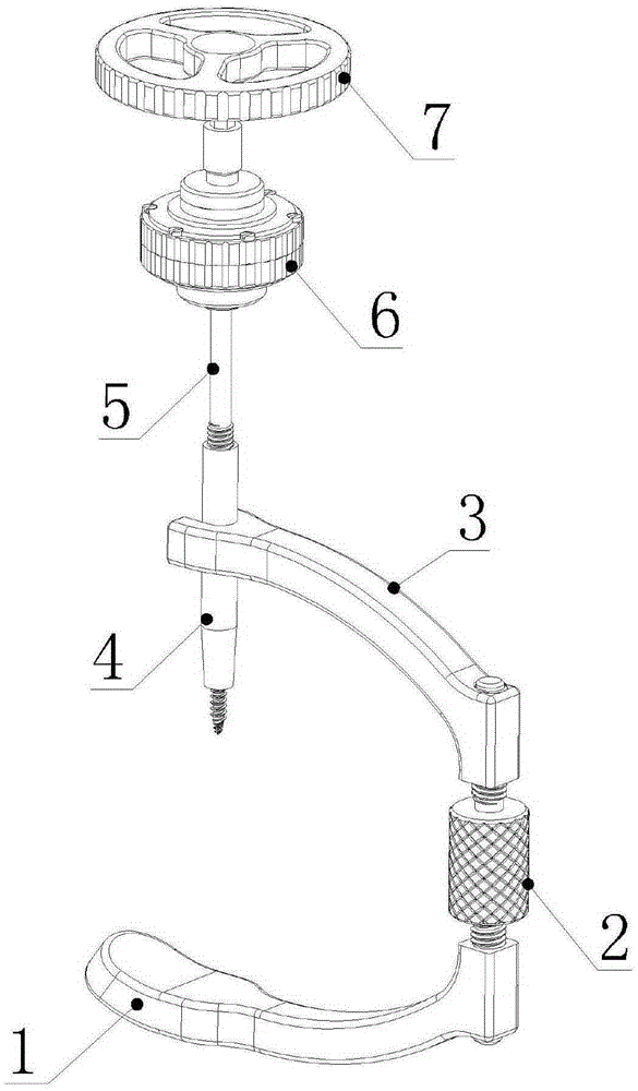
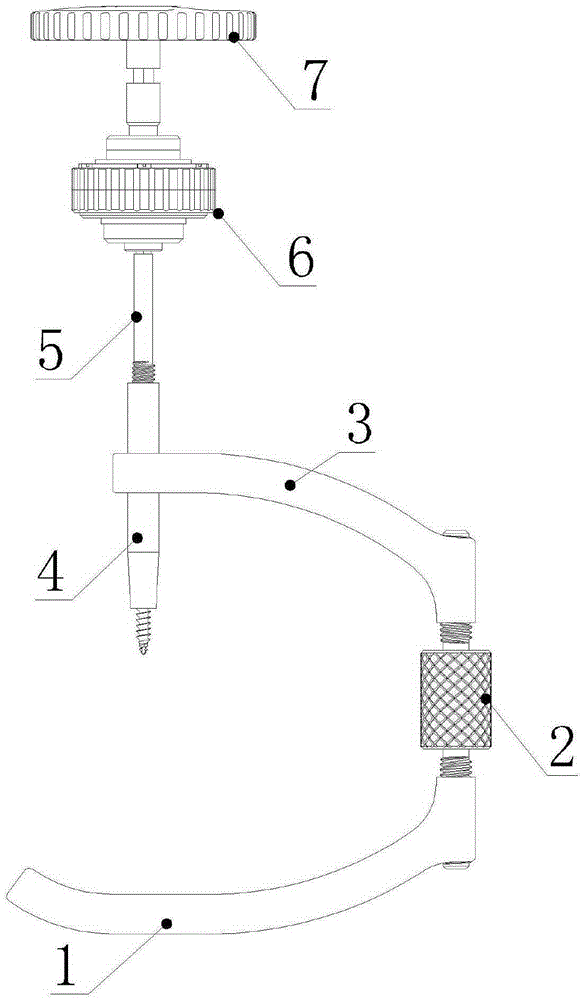
[0020] When the free-hand nail external fixation system is not in use, parts can be disassembled and put into a small storage box or a medical bag, and when assembled, all parts can be taken out for assembly and nailing.

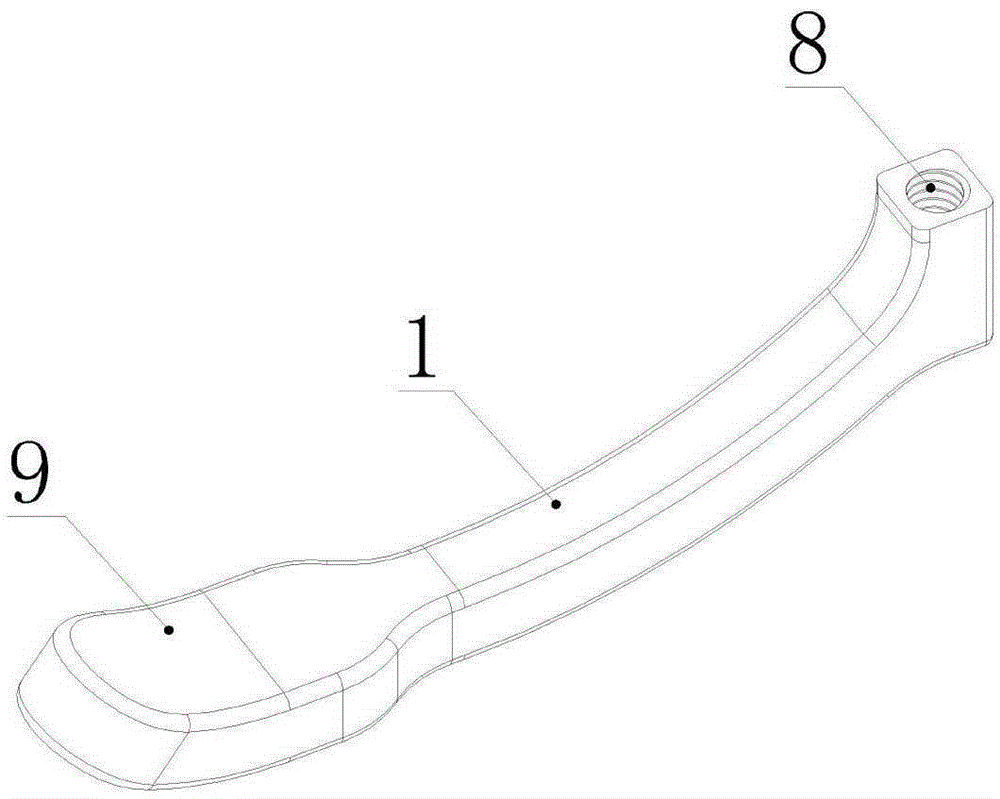
[0021] An external fixation system for free-hand nail placement, characterized in that the system is composed of an external fixation bracket, a gear pair mechanism 6, a bone nail 5 and a matching rotating handle 7, and the external fixation bracket is integrally formed into a three-sided closed tiger's mouth shape, and is composed of The lower curved rod 1, the vertical rod 2, the upper curved rod 3 and the threaded sleeve 4 are composed; the lower curved rod 1 and the vertical rod 2 are respectively provided with internal threads, and the tail end of the lower curved rod 1 is thickened Support base 9, the head section of the lower arc-shaped rod 1 is provided with a pipe hole 8 with internal thread; the head and tail ends of the vertical rod 2 are externall...


PUM


Abstract

The invention discloses a bare-handed nail implantation external fixation system, which is composed of an external fixing bracket, a gear pair mechanism, a bone nail and a matched rotary handle, wherein the external fixing bracket is integrally formed as a three-sided enclosed jaw-shaped structure, and the external fixing bracket is composed of an upper arc-shaped rod, a lower arc-shaped rod, a threaded vertical rod and a threaded casing; the gear pair mechanism is composed of a planetary gear pair that a big gear is driven by a small gear, and three bearings are configured inside the gear pair mechanism, so that the gear pair mechanism has an effect of triple torque amplification; the bone nail is a high-strength metal nail which has a self-tapped double-threaded head at the top, the bone nail is connected to a coarse thread which is used for fixing bone substance and the middle is provided with a pipe thread which is matched with the threaded casing. The external fixation system disclosed by the invention is designed for temporary fixation operations which are required for traumatic fractures in the case of natural disasters in the field or under severe environment of wars; the system can be assembled simply and can be operated by a single person without a power supply, and the system can be repeatedly used; by virtue of the labor-saving gear pair mechanism, nail implantation can be easily completed even by women; and the external fixation system, after being disassembled, is small in volume, light and convenient, and is easy to carry.

Description

technical field [0001] The invention relates to an external fixation system, in particular to a nail external fixation system for purely manual assembly devices in harsh outdoor environments. Background technique [0002] In the field environment, due to sudden natural disasters, wars, etc. caused by limb fractures, in order to avoid secondary trauma caused by collisions during the transfer process, or necrosis caused by long-term bone dislocation trauma to soft tissues, etc., it is necessary to Immediate immobilization of the fracture site. At present, for limb fracture trauma, internal plate fixation or external nail external fixation system is generally used clinically, which has a good recovery effect on fractures, but in the field environment, due to the lack of proper equipment conditions, this type of fixation is not performed on the wounded became very difficult. [0003] Most of the existing temporary fixation methods in the field are to clamp the fracture site of...

Claims


Application Information

Patent Timeline
IPC IPC(8): A61B17/60
CPCA61B17/60A61B2017/564
Inventor 尹庆水程顺巧张培发马向阳
Owner 广州聚生生物科技有限公司
Why Eureka
Try Eureka