
Multi-shaft parallel-connection cutting machining device

A cutting processing and parallel connection technology, applied in metal processing equipment, metal processing machinery parts, turning equipment, etc., can solve the problems of unsuitable to ensure the dynamic balance of the water pump, the overall shape of the water pump is irregular, and the processing efficiency is not high, so as to improve the processing efficiency of the equipment , Improve processing flexibility, and strong practicability

Active Publication Date: 2016-01-13
HENAN FEILONG WUHU AUTOMOBILE PARTS
View PDF5 Cites 2 Cited by
  • Summary
  • Abstract
  • Description
  • Claims
  • Application Information

AI Technical Summary

Problems solved by technology

The outer surfaces of these water inlets need to be installed with water pipes, and turning is required during processing. In the prior art, the turning of the outer end faces of the water inlet pipes is usually carried out in sequence, and the processing efficiency is not high. pipeline interference
In addition, the overall shape of the water pump is irregular, and it is difficult to clamp, and it is not suitable to ensure the dynamic balance of the water pump during turning.

Method used


Image

  • Multi-shaft parallel-connection cutting machining device
  • Multi-shaft parallel-connection cutting machining device
  • Multi-shaft parallel-connection cutting machining device

Examples


Embodiment Construction

[0025] In order to make the technical means and creative features realized by the present invention easy to understand, the present invention will be further elaborated below.

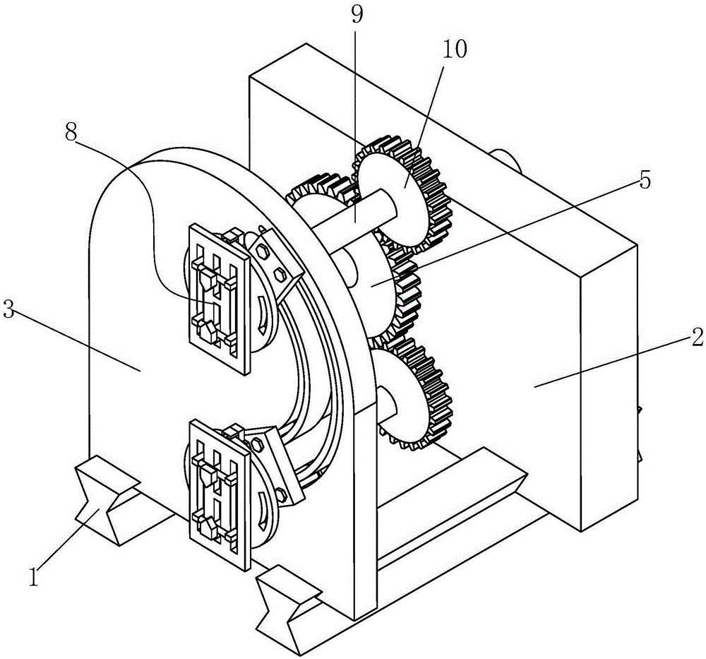
[0026] Such as Figure 1 to Figure 8 As shown, a multi-axis parallel cutting processing device includes a slide rail 1 on which a sliding support frame 2 and a sliding turntable 3 are matched.

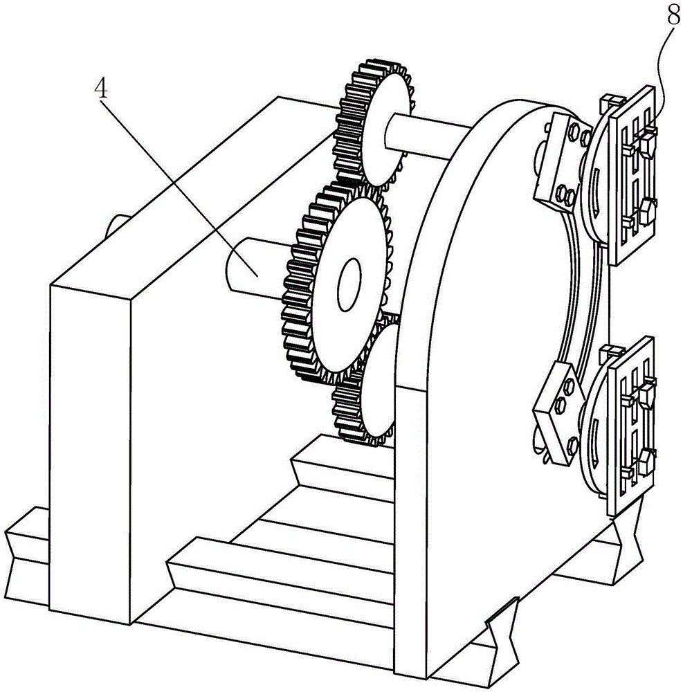
[0027] A bearing sleeve is installed in the sliding support frame 2, and a transmission shaft 4 is connected inside the bearing sleeve, and a driving gear 5 is installed at the front end of the transmission shaft 4.

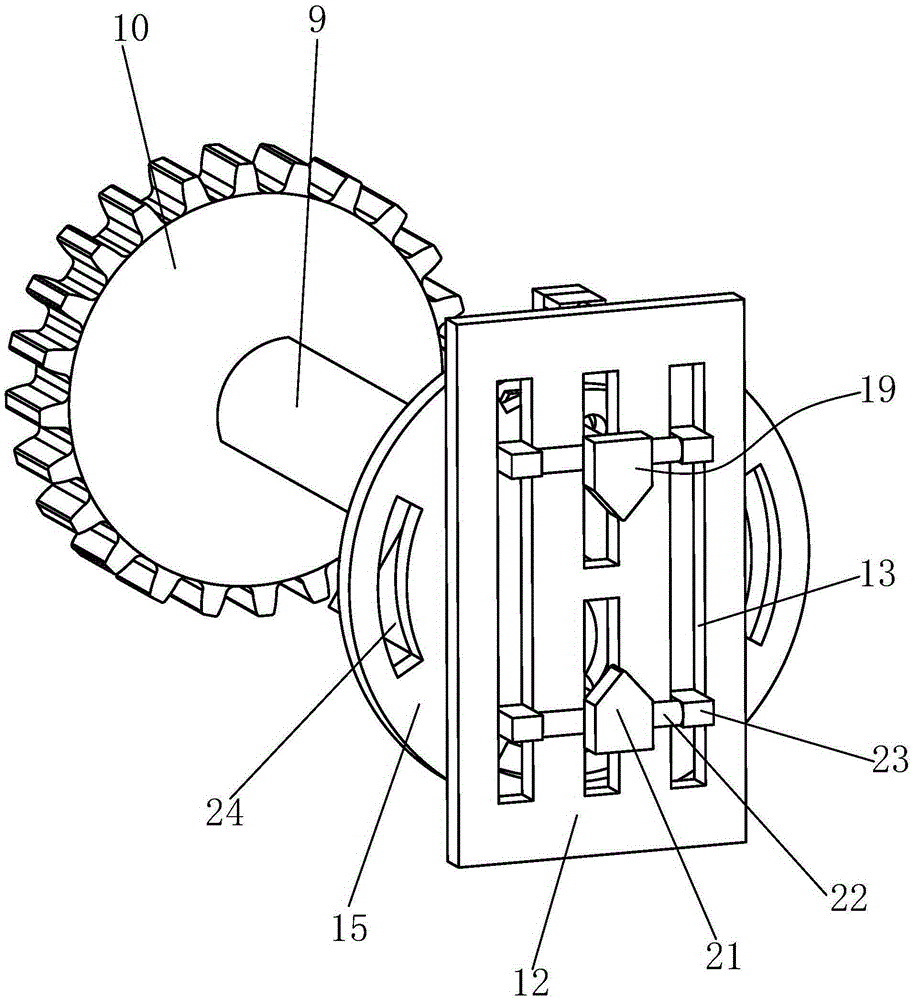
[0028] The sliding turntable 3 is provided with an arc-shaped slideway 6, the inside and outside of the arc-shaped slideway 6 are respectively provided with an arc-shaped positioning slideway 7, and there are two turning tool holders 8 in the arc-shaped slideway 6. . The arc-shaped slideway 6 is semicircular, so that the distance between the turning tool holders 8 in the arc-shaped slideway 6 ca...


PUM


Abstract

The invention relates to a multi-shaft parallel-connection cutting machining device. The multi-shaft parallel-connection cutting machining device comprises a sliding rail. The sliding rail is provided with a sliding supporting frame and a sliding rotary disc in a matched mode. A bearing sleeve is installed in the sliding supporting frame, and a transmission shaft is arranged in the bearing sleeve. A driving gear is installed at the front end of the transmission shaft. An arc slideway is arranged on the sliding rotary disc, the inner side and the outer side of the arc slideway are each provided with an arc positioning slideway, and two turning cutter frames can move on the arc slideway. Each turning cutter frame comprises a rotary shaft penetrating through the arc slideway. The rear end of each rotary shaft is provided with a driven gear matched with the driving gear. The front side of each rotary shaft is sleeved with a positioning block located in front of the sliding rotary disc. A plurality of bolts are installed on each positioning block, penetrate through the arc positioning slideway on the corresponding side and are matched with nuts. A plurality of parallel shafts can be machined simultaneously through the multi-shaft parallel-connection turning cutter frames. All turning cutters can be adjusted independently. The machining efficiency and machining flexibility are improved. Two shafts in different distances can be turned.

Description

technical field [0001] The invention relates to the technical field of auto parts processing equipment, in particular to a multi-axis parallel cutting processing device. Background technique [0002] In the cylinder block of the car engine, there are many water channels for cooling water circulation, which are connected with the radiator (commonly known as the water tank) placed in the front of the car through water pipes to form a large water circulation system. There is a water pump driven by the fan belt to pump the hot water out of the water channel of the engine block and pump the cold water in. There is also a thermostat next to the water pump. When the car is just started (cold car), it is not turned on, so that the cooling water does not pass through the water tank, but only circulates in the engine (commonly known as small circulation). When the temperature of the engine reaches above 95 degrees Celsius When it is turned on, the hot water in the engine is pumped in...

Claims


Application Information

Patent Timeline
IPC IPC(8): B23B3/32B23B21/00B23Q1/26
CPCB23B3/32B23Q1/262
Inventor 张锋梁建华闫飞
Owner HENAN FEILONG WUHU AUTOMOBILE PARTS
Learn More