Cylinder floating double active roller feeding mechanism

A dual-active, floating technology, which is applied in the manufacture of flat surface processing machines, wood processing appliances, workpiece feeding devices, etc., can solve the problems of long time consumption, low processing accuracy, increased raw material waste, etc., to save production. Cost, good feeding stability, and the effect of improving production efficiency

Active Publication Date: 2017-06-06
SICHUAN QINGCHENG MACHINERY
View PDF9 Cites 0 Cited by
  • Summary
  • Abstract
  • Description
  • Claims
  • Application Information

AI Technical Summary

Problems solved by technology

Although the currently popular four-sided planing machine has the advantages of multi-function and high efficiency, the straightening effect is poor
When the workpiece is not flat, it is still necessary to rely on plane planing and pressing planing for reciprocating planing, which not only increases the workload and work intensity, but also has low machining accuracy, and they are large in size, not compact in structure, and the operating procedures are cumbersome.
[0003] When the traditional four-sided planer transports wood, the unevenness of the wood is relatively large, that is, the material is bent, which leads to unstable feeding of the conveying mechanism, large vibration of the machine tool itself, and prone to material jamming and material breaking, increasing the Waste of raw materials, but also lead to a great impact on production efficiency
The current four-sided planer needs to adjust the workbench or feed rollers for wood with different unevenness to adapt to the wood transportation with different curvatures, but this kind of equipment is difficult to adjust, takes a long time, and the equipment structure is complicated and the cost is high.

Method used


Image

  • Cylinder floating double active roller feeding mechanism
  • Cylinder floating double active roller feeding mechanism
  • Cylinder floating double active roller feeding mechanism

Examples


Embodiment Construction

[0023] The present invention will be further described below in conjunction with the accompanying drawings, but the protection scope of the present invention is not limited to the following description.

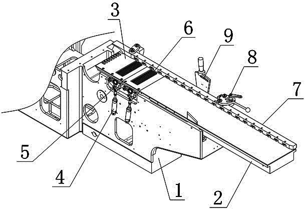
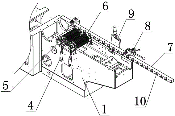
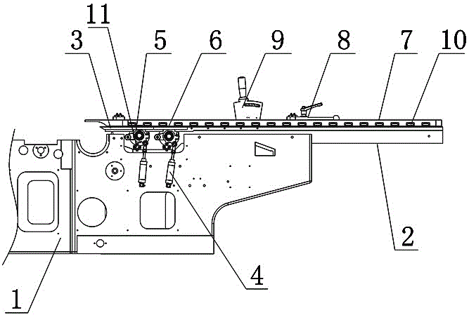
[0024] Such as figure 1 , figure 2 and image 3 As shown, the cylinder floating double active roller feeding mechanism includes body 1, movable table 2, cylinder 4, pendulum frame 5 and feeding roller 6, movable table 2 is installed on the top of body 1, and the upper part of movable table 2 is fixed A movable workbench mouth plate 3 is installed, two cylinders 4 are respectively arranged on the two side walls of the body 1, the tail of the cylinder 4 is hingedly installed on the side wall of the body 1, and each cylinder 4 is hinged with a pendulum 5 respectively, as Figure 5 As shown, the swing frame 5 includes a swing frame body 51, a cylinder connecting plate 53 and a hinge plate 54, the center of the swing frame body 51 is provided with a bearing hole 52, one side of...


PUM


Abstract

The invention relates to a cylinder floating type double-active-roller feeding mechanism. The mechanism comprises a machine body (1), a movable working table (2), cylinders (4), swing frames (5) and a feeding roller (6), wherein the movable working table (2) is mounted at the top of the machine body (1); two cylinders (4) are respectively arranged on two side walls of the machine body (1); the tail parts of the cylinders (4) are hinged to the side walls of the machine body (1); each cylinder (4) is hinged with one swing frame (5); the swing frames (5) comprise swing frame bodies (51), cylinder connecting plates (53) and hinge plates (54); the cylinder connecting plates (53) are arranged at one sides of the swing frame bodies (51), and the hinge plates (54) are arranged at the other sides; extension shafts of the cylinders (4) are hinged with the cylinder connecting plates (53); the hinge plates (54) are hinged with the machine body (1); and shafts at two ends of the feeding roller (6) are matched and connected with bearings in bearing holes (52) at two aides of the machine body (1). The cylinder floating type double-active-roller feeding mechanism has the advantages of good feeding stability, high efficiency and adjustment convenience.

Description

technical field [0001] The invention relates to the technical field of wood processing machinery, in particular to a cylinder floating double driving roller feeding mechanism. Background technique [0002] The four-sided planer is mainly used for processing wood products such as wooden squares, planks, decorative moldings, and wooden floors, and planing the upper, lower, and sides of the wood. Excellent four-sided planers are generally compact in structure, hard-coated on the work surface, durable, and the spindle is specially processed with better precision. For the feeding system, it is best to use a stepless speed regulation mechanism, and the universal joint is used to connect the transmission between the feeding roller and the deceleration mechanism, so that the transmission can be stable and the feeding can be powerful. Although the currently popular four-sided planing machine tools have the advantages of multi-function and high efficiency, the straightening effect is...

Claims


Application Information

Patent Timeline
Patent Type & Authority Patents(China)
IPC IPC(8): B27C1/08B27C1/12B27C1/14
Inventor 鲁素勤王云清
Owner SICHUAN QINGCHENG MACHINERY
Why Eureka
Try Eureka