Stacking machine lifting mechanism with high speed function

A lifting mechanism and stacker technology, applied in the direction of lifting devices, etc., can solve the problems of large linear pulling force, incapable of large pulling force, and high cost of the lifting mechanism, and achieve the effect of reducing local force, saving space, and reducing models.

Inactive Publication Date: 2016-01-13
HEFEI ZHONGDING INFORMATION TECH
View PDF5 Cites 0 Cited by
  • Summary
  • Abstract
  • Description
  • Claims
  • Application Information

AI Technical Summary

Problems solved by technology

[0002] The sprocket is often used for chain transmission in the lifting mechanism of the loading platform. Due to the variable transmission of the sprocket, it will cause obvious vibration. When running at high speed, the pulling force is not large, or the noise is large.
The existing lifting mechanism adopts pulleys fixedly arranged on the upper and lower beams of the stacker, and the linear pulling force on the lifting mechanism is relatively large, so it is necessary to select a high-power lifting reducer, which is costly

Method used


Image

  • Stacking machine lifting mechanism with high speed function

Examples


Embodiment Construction

[0016] A preferred embodiment of the present invention will be described in detail below with reference to the accompanying drawings.

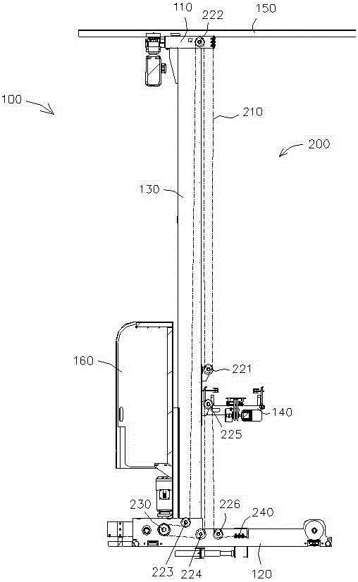
[0017] Such as figure 1 As shown, the stacker 100 is mainly composed of a sky rail 150, an upper beam 110, a column 130, a lower beam 120, a loading platform 140 and an electrical control part 160, wherein the column 130 is used to connect the upper and lower beams, and the loading The table 140 is connected with the column through guide wheels, and moves up and down along the column through the lifting mechanism 200 .

[0018] The lifting mechanism 200 includes a synchronous belt 210 and a pulley block and a drive wheel 230 for penetrating the synchronous belt. The synchronous belt 210 is the main component of the lifting transmission. The main consideration for the design of the synchronous belt is that the synchronous belt has no sinusoidal speed jump difference. The speed is in a steady state, and there is no vibration damage to the mecha...


PUM


Abstract

The invention provides a goods carrying table lifting mechanism used for a stacking machine, transmission is stable and free of vibration, and the space utilization rate is increased while the cost of the stacking machine is lowered. The lifting mechanism comprises a synchronous belt, a pulley block and a driving wheel, wherein the synchronous belt winds across the pulley block and the driving wheel. One end of the synchronous belt is fixedly arranged on an upper cross beam, and the other end of the synchronous belt is arranged on the lower cross beam through a tensioning device. The pulley block comprises a first movable pulley, a first fixed pulley, a second fixed pulley, a third fixed pulley, a second movable pulley and a fourth fixed pulley, wherein the synchronous belt winds across the first movable pulley, the first fixed pulley, the second fixed pulley, the third fixed pulley, the second movable pulley and the fourth fixed pulley in sequence; the first movable pulley and the second movable pulley are both arranged on a goods carrying table, the first fixed pulley is arranged on the upper cross beam, and the second fixed pulley, the third fixed pulley and the fourth fixed pulley are all arranged on the lower cross beam; the driving wheel is arranged between the second fixed pulley and the third fixed pulley.

Description

technical field [0001] The invention relates to the technical field of a stacker, in particular to a lifting mechanism of a stacker with a high-speed function. Background technique [0002] The sprocket is often used for chain transmission in the lifting mechanism of the loading platform. Due to the variable transmission of the sprocket, it will cause obvious vibration. When running at high speed, the pulling force cannot be large, or the noise is large. The existing lifting mechanism adopts pulleys fixedly arranged on the upper and lower beams of the stacker, and the linear pulling force on the lifting mechanism is relatively large, so a high-power lifting reducer needs to be selected, and the cost is relatively high. Contents of the invention [0003] The invention provides a stacker lifting mechanism with stable transmission and no vibration, which can reduce the cost of the stacker and improve the space utilization rate. [0004] In order to solve the problems o...

Claims


Application Information

Patent Timeline
Patent Type & Authority Applications(China)
IPC IPC(8): B66F9/20
Inventor 曹亮李群徐涛张小龙范圣罗刘德超刘宏庆邵华张苗
Owner HEFEI ZHONGDING INFORMATION TECH
Why Eureka
Try Eureka