
Device capable of measuring limited filling pressure and displacement produced when retaining wall rotates around wall bottom

A technology that rotates around the bottom of the wall and retains the wall. It is used in the testing of basic structures, buildings, artificial islands, etc. It can solve the problem of little model test research, and achieve the effect of simple structure, convenient operation and easy to master.

Inactive Publication Date: 2016-01-13
NORTH CHINA UNIV OF WATER RESOURCES & ELECTRIC POWER
View PDF4 Cites 9 Cited by
  • Summary
  • Abstract
  • Description
  • Claims
  • Application Information

AI Technical Summary

Problems solved by technology

At present, there are few model test studies on the law of soil pressure and displacement changes when the limited fill retaining wall rotates around the bottom of the wall

Method used


Image

  • Device capable of measuring limited filling pressure and displacement produced when retaining wall rotates around wall bottom
  • Device capable of measuring limited filling pressure and displacement produced when retaining wall rotates around wall bottom
  • Device capable of measuring limited filling pressure and displacement produced when retaining wall rotates around wall bottom

Examples


Embodiment 1

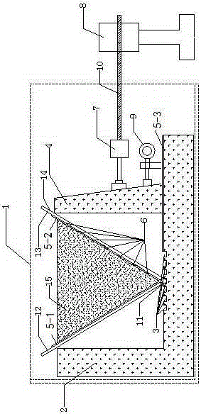
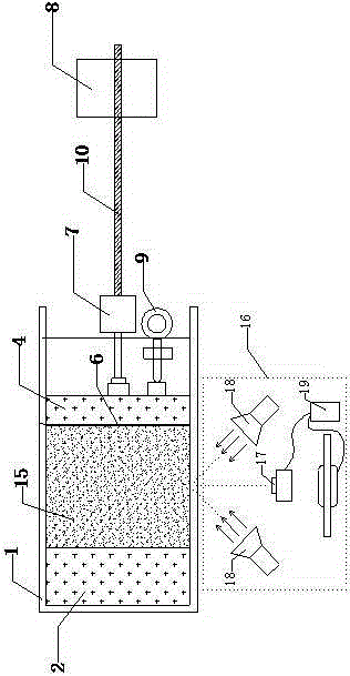
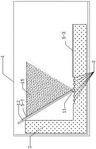
[0024] Embodiment 1: its front and rear sides of transparent plexiglass model box 1 are 500mm long and 400mm wide, and the left side is 400mm long and 200mm wide, and the bottom surface is 500mm long and 200mm wide, and the plexiglass plate thickness is 10mm; L The glyph concrete pouring block 2 has a length of 530mm, a width of 200mm, a height of 380mm, and a thickness of 80mm; a sawtooth groove 3, a depth of 5mm, a length of 200mm, a width of 15mm, and an interval of 10mm; the retaining wall 4, the wall height is 300mm, the upper bottom is 40mm, the lower bottom is 80mm, and the width is 200mm; the length of the first steel plate 12 and the second steel plate 13 are both 500mm, the width is 200mm, and the thickness is 5mm.

[0025] Put a layer of sandpaper on the inner side of the retaining wall, the steel plate and the bottom plate to ensure that the friction of the soil is consistent with the friction of the sandpaper, so as to eliminate the influence of the boundary on the...

Embodiment 2

[0037] Embodiment 2: This embodiment is basically the same as Embodiment 1, and the special feature is that the inclination angle of the slopes on both sides of the limited fill is changed, that is, by placing the hinges 11 in different sawtooth grooves 3, changing the first steel plate 12 and the angle between the second steel plate 13 to achieve. It can be used to study the influence of different limited fill slope angles on soil pressure and displacement when the retaining wall rotates around the bottom of the wall.

Embodiment 3

[0038] Embodiment 3: This embodiment is basically the same as the preceding embodiment, and the special feature is that the direction in which the second steel plate 13 rotates around the bottom of the wall is changed, even if the SDJ-1 type three-speed electric and other strain control shearing instruments 8 rotate around the wall to the left The bottom rotation can be used to study the change law of the soil pressure and displacement when the limited fill soil is passively damaged.


PUM


Abstract

The invention relates to a device capable of measuring limited filling pressure and displacement produced when a retaining wall rotates around a wall bottom. The device comprises a limited filling model box system, a system of the retaining wall rotating around the wall bottom and a PIV testing system. The testing device can truly simulate the natural stress state existing when the limited filling retaining wall rotates around the wall bottom, in other words, the soil stress state is the same as the soil state in the actual engineering. According to the testing device, high-precision soil pressure sensors are arranged on the retaining wall at equal height intervals, so that the limited filling soil pressure can be measured in real time; and a high-precision camera is arranged in right front of the model box, and meanwhile the PIV technology is adopted, so that a soil displacement image produced in the whole process when the retaining wall rotates around the wall bottom is measured in real time. According to the model testing device, operation is convenient, and related instruments are simple in structure and easy to master.

Description

technical field [0001] The invention relates to a geotechnical model test device for civil engineering, in particular to a device capable of measuring limited earth filling pressure and displacement when a retaining wall rotates around the bottom of the wall, which is applied to geotechnical tests of geotechnical engineering. Background technique [0002] Calculation of earth pressure acting on retaining structures is a key issue in geotechnical engineering design. Classical theory assumes that there is a semi-infinite soil mass behind the wall, and the deformation of the soil mass reaches the limit state. However, in actual engineering design, the displacement of the retaining wall is easily limited by the allowable displacement. The soil cannot reach the ultimate equilibrium state, and the earth pressure is between the static earth pressure and the limit earth pressure. For example, the foundation pit support structure adjacent to the existing basement, the slope retainin...

Claims


Application Information

Patent Timeline
Patent Type & Authority Applications(China)
IPC IPC(8): E02D33/00E02D29/02
Inventor 姜彤张俊然李洪军王忠福张昕郭萌萌
Owner NORTH CHINA UNIV OF WATER RESOURCES & ELECTRIC POWER
Learn More