
Cover structure for improving cooling efficiency of horizontal gas film on downstream of open slotted hole

A technology of air film cooling and slotted holes, which is applied in the direction of supporting components of blades, engine components, machines/engines, etc., and can solve the problems of insufficient collection of cooling air, raising cooling air, and hindering the flow of cooling air

Active Publication Date: 2016-01-13
HEBEI UNIV OF TECH
View PDF6 Cites 2 Cited by
  • Summary
  • Abstract
  • Description
  • Claims
  • Application Information

AI Technical Summary

Problems solved by technology

The Chinese patent (Patent No. 201010106756.6) proposes a structure to improve the efficiency of film cooling of discrete holes. This structure does not take into account the superimposed effect of film cooling on the wall surface by transverse grooves. The downstream protrusion is not only integrated with the wall surface, but also At the same time, it is close to the gas film hole, which hinders the flow of cooling gas to the downstream wall surface, and the protrusion raises the cooling gas, exposing the wall surface within a certain range near the protrusion to high-temperature gas, reducing the protective effect of the cooling gas film on the wall surface
The applicant's previous patent application (201520094208.4) proposed a structure to improve the film cooling efficiency of the downstream wall of the slotted film hole. The structure has transverse grooves and protrusions, but the patent still has the following shortcomings: The cooling air that is far away from the wall cannot be fully collected by the bulge, and this part of the cooling air rises when it encounters the bulge, which reduces the cooling efficiency of the wall near the bulge

Method used


Image

  • Cover structure for improving cooling efficiency of horizontal gas film on downstream of open slotted hole
  • Cover structure for improving cooling efficiency of horizontal gas film on downstream of open slotted hole
  • Cover structure for improving cooling efficiency of horizontal gas film on downstream of open slotted hole

Examples


Embodiment 1

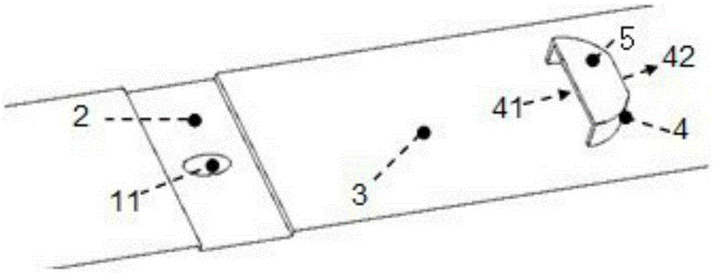
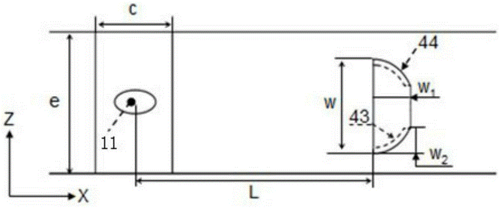
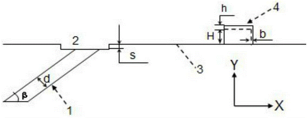
[0033] This embodiment improves the cover structure of the downstream transverse air film cooling efficiency of the slotted hole (see Figure 1-3 ) includes air film hole 1, transverse groove 2, wall 3, protrusion 4 and capping 5, the upstream area of ​​wall surface 3 is provided with air film hole 1, transverse groove 2 is provided at air film hole outlet 11, and protrusion 4 In the downstream area of ​​the wall surface 3, the protrusion is two brackets, and the two brackets are symmetrically arranged perpendicular to the wall surface 3 with the central line of the gas film hole as the axis, and the convex air inlet 41 is facing the direction of the gas film hole, and the back The direction of the air film hole is a raised air outlet 42, the profile line of the projection 4 facing the direction of the film hole is the windward profile 43, and the profile line facing away from the direction of the film hole is the back pressure profile 44 of the projection 4, The windward prof...

Embodiment 2

[0040] In this embodiment, the position and connection relationship of each part in the cover structure for improving the efficiency of lateral air film cooling downstream of the slotted hole are the same as in Embodiment 1, except that the protrusions 4 are two prism-shaped arcs (see Figure 8 ), the capping is a non-smooth curved surface shape, and the two sides of the capping are fixedly connected with the tops of two prism-type arcs respectively, and the thickness of the capping 5 is the aperture of the gas film hole 1 of 1 / 10.

Embodiment 3

[0042] In this embodiment, the position and connection relationship of each part in the cover structure to improve the efficiency of lateral air film cooling downstream of the slotted hole is the same as that of Embodiment 1, the protrusion 4 is two brackets, and the difference is that the capping is a smooth arc. surface (see Figure 9 ), the two sides of the capping are respectively fixedly connected with the tops of the two brackets, the thickness of the capping 5 is the aperture of the gas film hole 1 of 0.05, and the distance from the highest point of the capping 5 to the wall 3 is the height of the protrusion 4 2 times.

[0043] The unmentioned parts of the present invention are applicable to the prior art, especially the prior patent application of the applicant.


PUM


Abstract

The invention relates to a cover structure for improving the cooling efficiency of a horizontal gas film on the downstream of an open slotted hole. The cover structure comprises a gas film hole, a horizontal open slot, a wall, protrusions and caps. The gas film hole is formed in the upstream area of the wall. The horizontal open slot is formed in an air outlet of the gas film hole. The protrusions are arranged in the downstream area of the wall and are distributed with the central line of the wall passing through the center of the air outlet of the gas film hole as the axis of symmetry. The face, facing the air outlet of the gas film hole, of each protrusion is a protrusion air inlet, and the opposite is a protrusion air outlet. The ratio of the length of each protrusion air inlet to the aperture of the gas film hole ranges from 2.0 to 5.0, and the length of each protrusion air inlet is 1.5-5.0 times that of the corresponding protrusion air outlet. The distance from each protrusion air inlet to the center of the air outlet of the gas film hole is 10-30 times the aperture of the gas film hole. The ratio of the height of the protrusions to the aperture of the gas film hole ranges from 0.25 to 3.0. The cover structure is characterized by further comprising the caps which cover the protrusions; the two sides of each cap are fixedly connected with the top of the corresponding protrusion; and the thickness of the caps is not greater than one fifth of the aperture of the gas film hole.

Description

technical field [0001] The invention relates to the technical field of blade cooling inside a gas turbine, in particular to a cover structure for improving the cooling efficiency of the transverse air film downstream of a slotted hole. Background technique [0002] As an important power device, gas turbine is widely used in aerospace, chemical industry, vehicle, power generation and other fields. The development of gas turbines marks a country's technological level, military strength and comprehensive strength. The thermal efficiency and output power of the gas turbine are mainly affected by the gas temperature. At this stage, the initial temperature of the inlet of the gas turbine is mainly increased by continuously developing high-temperature resistant materials and adopting cooling technology. However, due to the limitation of the development of high-temperature-resistant materials, effective cooling methods must be used to prevent the hot-end parts of the gas turbine fr...

Claims


Application Information

Patent Timeline
IPC IPC(8): F01D5/18
Inventor 王进崔沛刘祎炜闵春华朱恒宣
Owner HEBEI UNIV OF TECH
Learn More