
Pipe system hanging device of coal economizer

A technology of economizer pipe and hanging device, which is applied in the direction of pipe supports, pipes/pipe joints/pipes, mechanical equipment, etc., can solve the fatigue cracks of pipe clamps and header welds, and the inability of economizer pipes to pass through ventilation beams. Problems such as hanging, falling of pipe system, etc.

Active Publication Date: 2016-01-13
WUXI HUAGUANG BOILER
View PDF8 Cites 2 Cited by
  • Summary
  • Abstract
  • Description
  • Claims
  • Application Information

AI Technical Summary

Problems solved by technology

However, the economizer pipe system here cannot be supported by the ventilation beam. The usual fixing method is to use pipe clamps to directly weld the economizer upper header. Under the scouring of the pipe, it is easy to swing periodically, and the weld between the pipe clamp and the header is prone to fatigue cracks, which will eventually lead to the fall of the pipe system

Method used


Image

  • Pipe system hanging device of coal economizer
  • Pipe system hanging device of coal economizer

Examples


Embodiment Construction

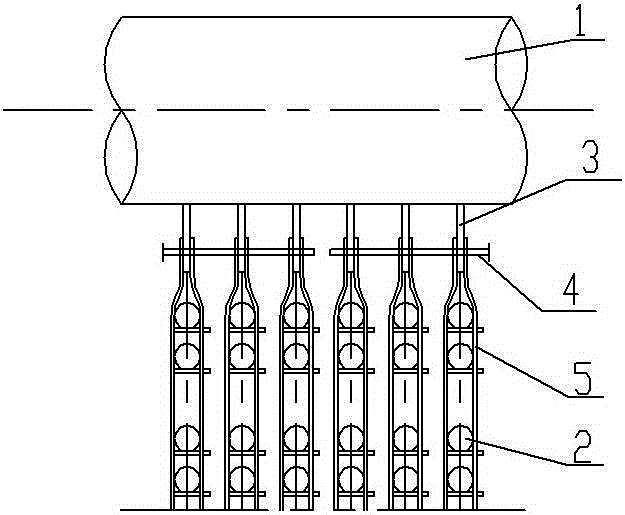
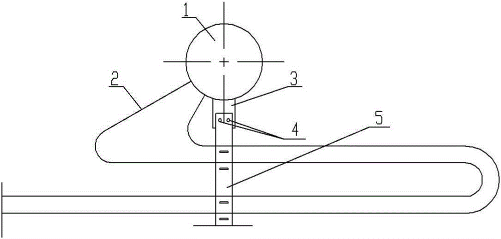
[0011] See figure 1 , figure 2 As shown, an economizer pipe system hanging device includes an upper header 1, a pipe clip 5 is arranged at the lower end of the upper header 1, an economizer pipe 2 is arranged inside the pipe clip 5, and the bottom of the upper header 1 is fixed A pre-embedded steel plate 3 is installed, and the pre-embedded steel plate 3 and the top of the pipe clamp 5 respectively have matching fixing holes, and the round steel 4 is welded through the fixing holes.

[0012] Six pre-embedded steel plates 3 are fixedly installed at the bottom of the upper header 1, and six corresponding pipe clamps 5 are installed at the lower end of the upper header 1, and each round steel 4 runs through three pre-embedded steel plates 3, and the round steel 4 and the pipe clamp 5 Solder connection on top.

[0013] Each pre-embedded steel plate 3 and the top of the pipe clamp 5 are respectively provided with two fixing holes, and each fixing hole runs through the round stee...


PUM


Abstract

The invention relates to the technical field of coal economizer structures of pulverized coal furnaces and circulating fluidized beds, in particular to a pipe system hanging device of a coal economizer. It can be guaranteed that coal economizer pipes are stably fixedly connected with an upper header, and the phenomenon of disengaging cannot happen. The pipe system hanging device comprises the upper header. Pipe clamps are arranged at the lower end of the upper header and internally provided with the coal economizer pipes. The pipe system hanging device is characterized in that embedded metal plates are fixedly installed at the bottom of the upper header, matched fixing holes are formed in embedded metal plates and the tops of the pipe clamps respectively, and connecting rods penetrate the fixing holes in a welding manner.

Description

technical field [0001] The invention relates to the technical field of economizer structures for pulverized coal furnaces and circulating fluidized beds, in particular to an economizer pipe system hanging device. Background technique [0002] In pulverized coal boilers and circulating fluidized beds, the tail flue space is limited, and a first-level economizer is often arranged in the cladding wall to reduce the temperature of the flue gas and increase the temperature of the feed water entering the steam drum. However, the economizer pipe system here cannot be supported by the ventilation beam. The usual fixing method is to directly weld the pipe clamp to the upper header of the economizer. Under the scouring of the pipe, it is easy to swing periodically, and the weld between the pipe clamp and the header is prone to fatigue cracks, which will eventually lead to the fall of the pipe system. Contents of the invention [0003] In order to solve the above problems, the prese...

Claims


Application Information

Patent Timeline
IPC IPC(8): F16L3/08
CPCF16L3/08
Inventor 杨念花卉任孝明薛志芳张春华
Owner WUXI HUAGUANG BOILER
Learn More