LED lamp with water-proof and dust-proof function

A LED lamp, waterproof and dustproof technology, which is applied in the direction of air-proof/waterproof devices, components of lighting devices, cooling/heating devices of lighting devices, etc., can solve problems such as unstable quality, poor light quality, and insufficient performance. Achieve good heat dissipation stability, increase heat dissipation effect, and increase heat dissipation effect

Inactive Publication Date: 2016-01-13
广东雪莱特光电科技股份有限公司
View PDF7 Cites 5 Cited by
  • Summary
  • Abstract
  • Description
  • Claims
  • Application Information

AI Technical Summary

Problems solved by technology

[0006] The purpose of the present invention is to provide an LED lamp with better heat dissipation efficiency and waterproof and dustproof function, so as to overcome the problems of poor light quality, insufficient performance, unstable quality, and poor waterproof and dustproof effect of high-power LED lamps currently on the market.

Method used


Image

  • LED lamp with water-proof and dust-proof function
  • LED lamp with water-proof and dust-proof function
  • LED lamp with water-proof and dust-proof function

Examples


Embodiment 1

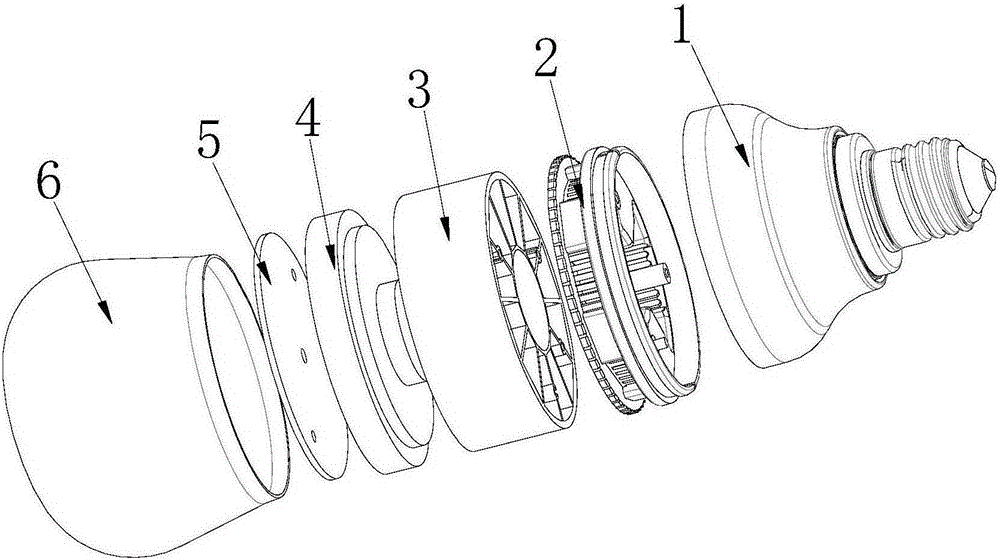
[0039] Such as figure 1 The LED lamp shown includes a lamp cap 1 , a connector 2 , a heat sink 3 , an isolation block 4 , a light source board 5 and a lampshade 6 . The connecting piece 2 is located between the lamp cap 1 and the heat sink 3 , and is used for connecting the lamp cap 1 and the heat sink 3 . The isolation block 4 is located between the heat sink 3 and the lampshade 6 for connecting the heat sink 3 and the lampshade 6 . The light source board 5 is installed on the isolation block 4 and is on the side facing the lampshade 6 .

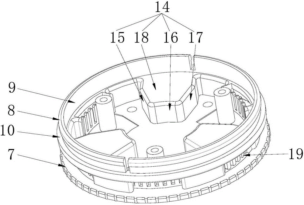
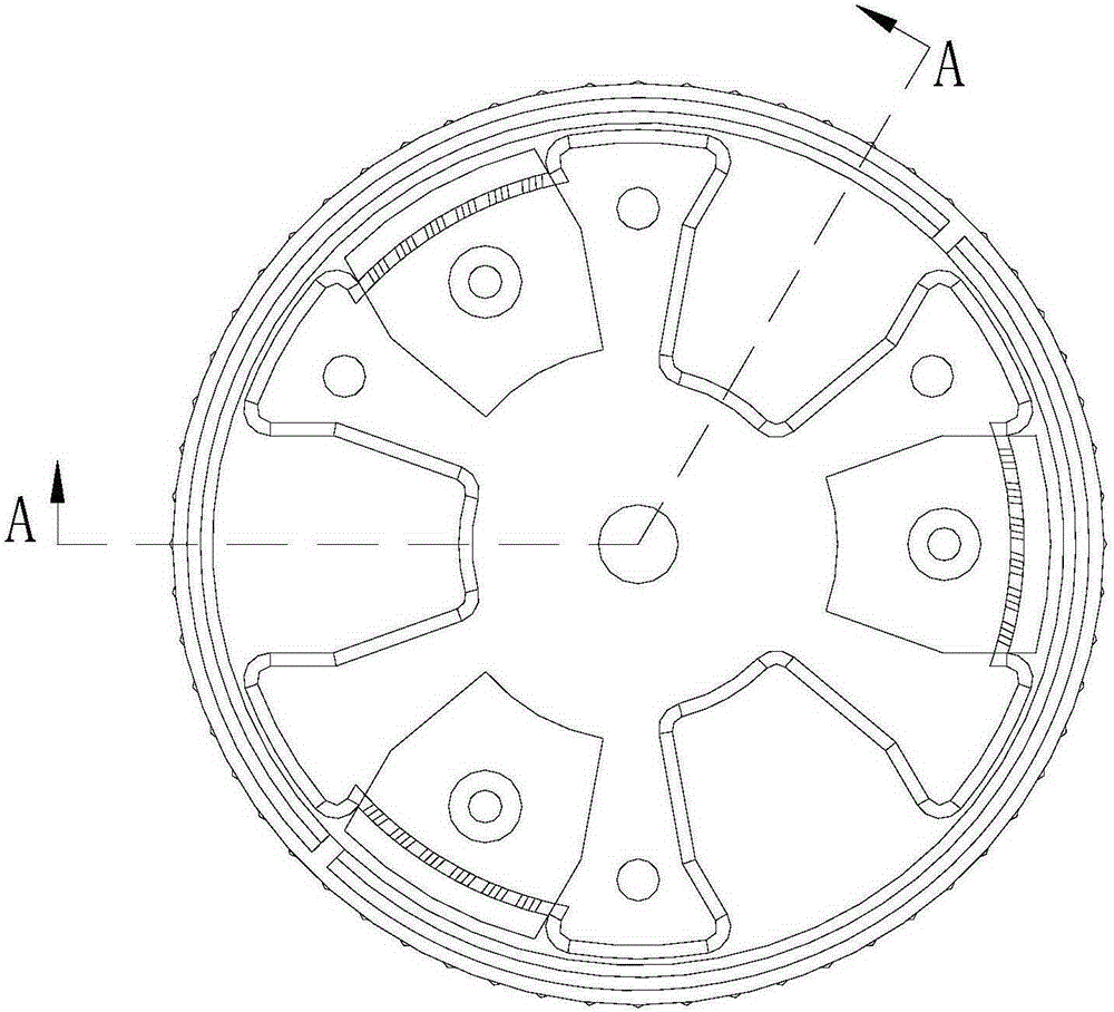
[0040] Such as Figure 2-5 , 11, in this embodiment 1, the outer contour of the connecting piece 2 is cylindrical, and the connecting piece 2 includes a bottom plate 7 and a connecting block 8 . In the first embodiment, the outer contour of the bottom plate 7 is cylindrical, and a connecting block 8 with a cylindrical outer contour is connected to the bottom plate 7 . An accommodating cavity 9 is formed in the connection block 8 . Alon...

Embodiment 2

[0047] The difference between this embodiment 2 and embodiment 1 is that, as Figure 12-15 As shown, in the second embodiment, three third exhaust holes 33 are provided on the connecting block 8 along the circumference of the connecting block 8 , and the third exhaust holes 33 communicate with the accommodating cavity 9 . The third exhaust hole 33 communicates with the accommodating chamber 9 to form a second air channel of the air convection element. A blocking block 19 is also arranged in each third exhaust hole 33 , and the blocking block 19 is located in the protective edge 10 , and the air vent 22 is also formed on the blocking block 19 . The protective edge 10 protects the blocking block 19 to prevent the blocking block 19 from being damaged due to external force collision. In order to prevent foreign objects from easily entering the accommodating cavity 9 , the height of the blocking block 19 can be greater than the height of the third exhaust hole 33 . Several air ho...

Embodiment 3

[0049] The difference between this embodiment 3 and embodiment 2 is that, as Figure 16-18 As shown, in the third embodiment, the base plate 7 is provided with a first ventilation hole 35 . The first ventilation hole 35 communicates with the accommodating chamber 9 and communicates with the inner tube 25 of the cooling seat 3 , constituting the third air channel of the air convection element. In addition, a second ventilation hole 36 is provided on the isolation block 4 , and the second ventilation hole 36 runs through the entire isolation block 4 and communicates with the inner tube 25 of the heat sink 3 . The light source board 5 is provided with a process hole, so that the second ventilation hole 36 can communicate with the inside of the lampshade 6 . When the LED lamp is working, after the air in the lampshade is heated, it can enter the inner tube of the heat sink along the second ventilation hole 36, and enter the third air flow channel through the first ventilation hol...


PUM


Abstract

The invention discloses an LED lamp with water-proof and dust-proof functions. The LED lamp with the water-proof and dust-proof functions comprises a lamp holder shell, a lampshade, a light source plate and a radiating base, wherein a plurality of ventilating passages for air circulation are formed inside the radiating base; an insulating block used for connecting the radiating base and the lampshade is arranged between the radiating base and the lampshade; a step part is formed in one side, facing to the radiating base, of the insulating block, the radiating base is attached to the step part, and an air inlet communicated with the ventilating passages is informed between the radiating base and the insulating block; one side, facing to the lampshade, of the insulating block, extends to form a stopping edge with a surrounding periphery, and the light source plate and the lampshade are mounted inside the stopping edge; a connecting piece used for connecting the radiating base and the lamp holder shell is further arranged between the radiating base and the lamp holder shell; a plurality of exhaust passages communicated with the ventilating passages and the outside are further arranged on the connecting piece; and the air inlet, the ventilating passages and the exhaust passages are in communication in sequence to form air circulation passages. According to the LED lamp provided by the invention, air circulation heat dissipation is performed through the ventilating passages, and the insulating block is used for preventing the light source plate from being impacted by water and dust.

Description

technical field [0001] The invention relates to the field of lamp lighting, in particular to an LED lamp with waterproof and dustproof functions. Background technique [0002] As an emerging green light source, LED has many advantages such as energy saving and environmental protection, and has been increasingly applied to various lighting fields. With the continuous development of LED technology, the power of the current LED light source is already very high, which can emit high-brightness light. This high-power LED has been applied to lighting equipment for various large venues. Although high-power LEDs can emit high-brightness light, limited by technology, the efficiency of converting electrical energy into light energy has not yet reached 100%. At present, the conversion efficiency of high-power LEDs produced by some manufacturers with more advanced technologies can also reach 100%. About 80%, about 20% of the electric energy is still converted into heat energy. If the ...

Claims


Application Information

Patent Timeline
IPC IPC(8): F21S2/00F21V29/83F21V29/50F21V31/03F21Y101/02
CPCF21V31/03
Inventor 周俊良吴彬源杨应森
Owner 广东雪莱特光电科技股份有限公司
Why Eureka
Try Eureka