Vapor compression-jet coupled refrigeration cycle device and method

A refrigeration cycle and steam technology, which is applied in refrigerators, refrigeration components, refrigeration and liquefaction, etc., can solve the problems of increasing compressor power consumption, reducing evaporator heat exchange efficiency and cooling capacity, etc., to reduce gas transmission volume, The effect of reducing power consumption and improving cooling capacity

Active Publication Date: 2017-09-19
SOUTHEAST UNIV
View PDF7 Cites 0 Cited by
  • Summary
  • Abstract
  • Description
  • Claims
  • Application Information

AI Technical Summary

Problems solved by technology

[0002] In the traditional compression refrigeration cycle, the liquid refrigerant cooled and condensed by the condenser will flash out gaseous refrigerant when throttling, and this part of gaseous refrigerant will not only not generate cold energy in the evaporator after entering the evaporator, but will also occupy The heat transfer area of ​​the evaporator affects the evaporation of liquid refrigerant, thereby reducing the heat transfer efficiency and cooling capacity of the evaporator. At the same time, this part of the low-pressure gas that does not produce cooling capacity will be sucked into the compressor, increasing the power consumption of the compressor.

Method used


Image

  • Vapor compression-jet coupled refrigeration cycle device and method
  • Vapor compression-jet coupled refrigeration cycle device and method

Examples


Embodiment Construction

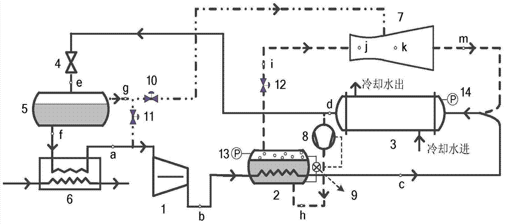
[0015] Compared with the ordinary refrigeration system, a vapor compression-jet coupled refrigeration cycle device utilizing the exhaust sensible heat of the refrigeration compressor of the present invention increases:

[0016] A gas-liquid separator for separating the flashed gaseous refrigerant after throttling;

[0017] A booster pump for boosting the pressure of the condensed liquid refrigerant;

[0018] A liquid level controller for sensing the liquid level of the generator and controlling the start and stop of the booster pump;

[0019] A steam generator set up to use the sensible heat of the exhaust of the compressor to generate higher pressure working steam for the operation of the ejector;

[0020] Ejectors for injecting throttling flashed gaseous refrigerant;

[0021] Several solenoid valves for switching processes and controlling flow;

[0022] Several pressure transducers are used to measure the pressure of the container.

[0023] This system can effectively im...


PUM


Abstract

The present invention is a vapor compression-jet coupled refrigeration cycle device and method utilizing the exhaust sensible heat of a refrigeration compressor, which includes a compressor, a generator, a condenser, a throttle valve, a gas-liquid separator, and an evaporator , injectors, liquid booster pumps, liquid level controllers, solenoid valves, pressure sensors, etc. The circulation system uses the superheated steam from the exhaust port of the refrigeration compressor to heat the condensed saturated liquid refrigerant sent by the booster pump in the gasification generator to generate saturated gas under the generation pressure, which is used as an injection throttling After the flash gas separated by the gas-liquid separator is used for the working steam of the ejector, the flash gas generated after being throttled by the throttle valve is separated by the gas-liquid separator and injected into the condenser by the ejector, so that not only It prevents the flash gas from entering the evaporator so that the limited heat exchange area of ​​the evaporator cannot be well utilized. Under the premise of the same cooling capacity, the air delivery volume of the compressor must be reduced, thereby reducing the power consumption of the compressor.

Description

technical field [0001] The invention relates to a vapor compression-jet coupled refrigeration cycle system utilizing the exhaust sensible heat of a refrigeration compressor, which can effectively improve the heat transfer coefficient of an evaporator, reduce the power consumption of a compressor, and thereby increase the refrigeration coefficient. Background technique [0002] In the traditional compression refrigeration cycle, the liquid refrigerant cooled and condensed by the condenser will flash out gaseous refrigerant when throttling, and this part of gaseous refrigerant will not only not generate cooling capacity in the evaporator after entering the evaporator, but will also occupy The heat transfer area of ​​the evaporator affects the evaporation of the liquid refrigerant, thereby reducing the heat transfer efficiency and cooling capacity of the evaporator. At the same time, this part of the low-pressure gas that does not produce cooling capacity will be sucked into the...

Claims


Application Information

Patent Timeline
Patent Type & Authority Patents(China)
IPC IPC(8): F25B25/00F25B41/04F25B41/06F25B49/02F25B41/20F25B41/30
Inventor 杜垲江巍雪李舒宏李彦军
Owner SOUTHEAST UNIV
Why Eureka
Try Eureka