Inner-fin heat pipe

A technology of heat pipes and fins, which is applied in the field of inner fin heat pipes, can solve the problems of heat pipe heat transfer coefficient reduction, local uneven heat transfer, uneven heat transfer, etc., to reduce fluid pressure, avoid local overheating, and extend heat pipes The effect of longevity

Inactive Publication Date: 2016-01-13
重庆神彩新型散热器有限公司
View PDF4 Cites 2 Cited by
  • Summary
  • Abstract
  • Description
  • Claims
  • Application Information

AI Technical Summary

Problems solved by technology

[0004] Generally, a heat pipe includes an evaporating end and a condensing end. The fluid in the evaporating section absorbs heat and evaporates, condenses at the condensing end, and transfers heat to the external fluid. Whether it is the evaporating end or the condensing end, there will be gas in the heat exchange process. In the case of liquid two-phase flow, and with the aging of the heat pipe, some non-condensable gas will be generated in the heat pipe, resulting in a decrease in the heat transfer coefficient of the heat pipe
[0005] In addition, during the heat exchange process between the evaporating end and the condensing end of the heat pipe, the heat transfer at each position of the evaporating end and the condensing end is different, resulting in uneven local heat transfer
[0006] In view of the above problems, the present invention provides a new heat pipe, thereby solving the problems of low heat transfer coefficient and uneven heat transfer in the case of heat pipe heat exchange

Method used


Image

  • Inner-fin heat pipe
  • Inner-fin heat pipe
  • Inner-fin heat pipe

Examples


Embodiment Construction

[0048] The specific embodiments of the present invention will be described in detail below in conjunction with the accompanying drawings.

[0049] In this article, if there is no special explanation, when it comes to formulas, " / " means division, and "×" and "*" mean multiplication.

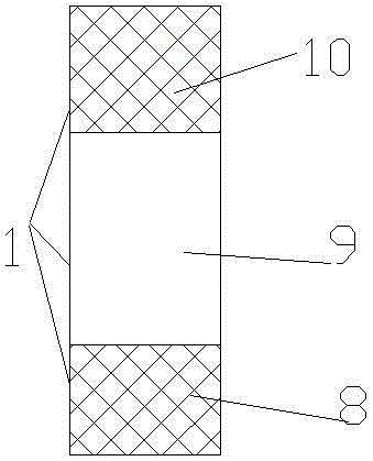
[0050] like figure 1 As shown, a heat pipe 1 includes an evaporating end 8 and a condensing end 10, and preferably also includes an adiabatic end 9. The evaporating end 8 absorbs heat, the fluid sealed in the heat pipe evaporates, and then the fluid enters the condensing end 10, and the heat is transferred through the condensing end to the outside, and then the fluid after heat exchange becomes a liquid, and then flows to the evaporation end 8.

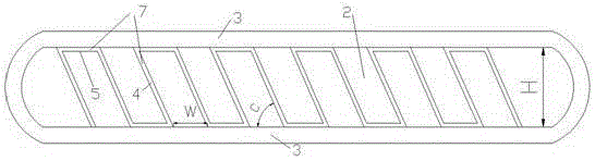
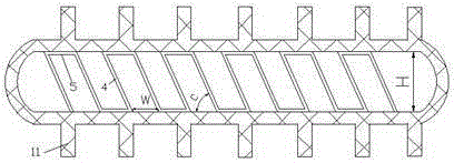
[0051] like figure 2 As shown, the heat pipe 1 includes a flat tube, and the flat tube includes tube walls 3 parallel to each other, and a fluid channel 2 is formed between the adjacent tube walls 3 . Fins 7 are arranged inside the flat tube 1 , pref...


PUM


Abstract

The invention provides a heat pipe. The heat pipe comprises a flat pipe, wherein the flat pipe comprises parallel pipe walls; a fluid channel is formed between the adjacent pipe walls. The heat pipe comprises fins arranged in the flat pipe, and the fins are arranged between the pipe walls; the fins comprise inclined portions inclining to the pipe walls, and protrusions are machined on the inclined portions in a stamped manner, so that fluid on the two sides of the inclined portions is continuous through holes formed in the inclined portions in a stamped manner; and the protrusions extend outwards from the inclined portions in the flowing direction of the fluid. Stamped protruded plate fin heat dissipation pieces are arranged in the heat pipe, and therefore the problem that the heat exchange efficiency of the noncondensable gas is low is solved, energy is greatly saved, and the problem that the heat exchange efficiency of the heat pipe is low is solved.

Description

technical field [0001] The invention belongs to the field of heat pipes, in particular to an inner fin heat pipe. Background technique [0002] Heat pipe technology is a heat transfer element called "heat pipe" invented by George Grover of the Los Alamos National Laboratory in the United States in 1963. It makes full use of the principle of heat conduction and the rapid The property of heat transfer, the heat of the heating object is quickly transferred to the outside of the heat source through the heat pipe, and its thermal conductivity exceeds that of any known metal. [0003] Heat pipe technology was widely used in aerospace, military and other industries before. Since it was introduced into the radiator manufacturing industry, people have changed the traditional radiator design ideas and got rid of the single heat dissipation mode that only relies on high air volume motors to obtain better heat dissipation. The use of heat pipe technology enables the radiator to obtain ...

Claims


Application Information

Patent Timeline
Patent Type & Authority Applications(China)
IPC IPC(8): F28D15/02F28F1/42
Inventor 李鸿钧朱达祥默宁王衍昊霍岩超刘晨中赵炜
Owner 重庆神彩新型散热器有限公司
Why Eureka
Try Eureka