An inner fin heat pipe with gradually changing protrusion length

A technology of heat pipes and fins, applied in the field of inner fin heat pipes, can solve the problems of heat pipe heat transfer coefficient reduction, local uneven heat transfer, uneven heat transfer, etc., achieve small flow resistance, avoid local overheating, and achieve heat dissipation effects Good results

Active Publication Date: 2016-11-16
常熟东南高新技术创业服务有限公司
View PDF3 Cites 0 Cited by
  • Summary
  • Abstract
  • Description
  • Claims
  • Application Information

AI Technical Summary

Problems solved by technology

[0004] Generally, a heat pipe includes an evaporating end and a condensing end. The fluid in the evaporating section absorbs heat and evaporates, condenses at the condensing end, and transfers heat to the external fluid. Whether it is the evaporating end or the condensing end, there will be gas in the heat exchange process. In the case of liquid two-phase flow, and with the aging of the heat pipe, some non-condensable gas will be generated in the heat pipe, resulting in a decrease in the heat transfer coefficient of the heat pipe
[0005] In addition, during the heat exchange process between the evaporating end and the condensing end of the heat pipe, the heat transfer at each position of the evaporating end and the condensing end is different, resulting in uneven local heat transfer
[0006] In view of the above problems, the present invention provides a new heat pipe, thereby solving the problems of low heat transfer coefficient and uneven heat transfer in the case of heat pipe heat exchange

Method used


Image

  • An inner fin heat pipe with gradually changing protrusion length
  • An inner fin heat pipe with gradually changing protrusion length
  • An inner fin heat pipe with gradually changing protrusion length

Examples


Embodiment Construction

[0047] The specific embodiments of the present invention will be described in detail below with reference to the accompanying drawings.

[0048] In this article, if there are no special instructions, when it comes to formulas, " / " means division, and "×" and "*" mean multiplication.

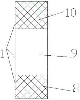
[0049] Such as figure 1 As shown, a heat pipe 1 includes an evaporating end 8, a condensing end 10, preferably an adiabatic end 9, the evaporating end 8 absorbs heat, the fluid sealed in the heat pipe evaporates, and then the fluid enters the condensing end 10, and the heat is transferred through the condensing end To the outside, the fluid after the heat exchange becomes liquid, and then flows to the evaporation end 8.

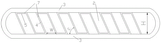
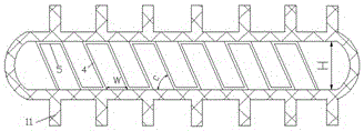
[0050] Such as figure 2 As shown, the heat pipe 1 includes a flat tube, and the flat tube includes tube walls 3 parallel to each other, and a fluid channel 2 is formed between the adjacent tube walls 3. A fin 7 is provided inside the flat tube 1, and it is preferable to provide a fin...


PUM


Abstract

The invention provides a heat pipe, comprising a flat tube, the flat tube includes tube walls parallel to each other, a fluid passage is formed between the adjacent tube walls, the heat pipe includes fins arranged in the flat tube, and the fins The fins are arranged between the tube walls, and the fins include an inclined part inclined to the tube wall, and the protrusions are processed on the inclined part by stamping, so that the fluid on both sides of the inclined part communicates through the holes formed by stamping on the inclined part; The protrusions extend outward from the inclined portion along the fluid flow direction, the length of the protrusions is L, and a plurality of protrusions are provided on the same inclined portion, and along the fluid flow direction, the length L of the same inclined portion becomes more and more bigger. The invention makes the heat pipe achieve the best heat dissipation effect and the smallest flow resistance through the regular change of the protrusion length.

Description

Technical field [0001] The invention belongs to the field of heat pipes, and particularly relates to an inner fin heat pipe. Background technique [0002] Heat pipe technology is a kind of heat transfer element called "heat pipe" invented by George Grover of the Los Alamos National Laboratory in the United States in 1963, which makes full use of the principle of heat conduction and phase change medium The rapid heat transfer properties of the heat pipe can quickly transfer the heat of the heating object to the heat source, and its thermal conductivity exceeds the thermal conductivity of any known metal. [0003] Heat pipe technology used to be widely used in aerospace, military and other industries. Since being introduced into the radiator manufacturing industry, people have changed the design thinking of traditional radiators and got rid of the single heat dissipation mode that relies solely on high-air-volume motors to obtain better heat dissipation. The use of heat pipe technol...

Claims


Application Information

Patent Timeline
Patent Type & Authority Patents(China)
IPC IPC(8): F28D15/04F28F1/42F28F1/02
CPCF28D15/0233F28D15/046
Inventor 李鸿钧朱达祥默宁王衍昊霍岩超刘晨中赵炜
Owner 常熟东南高新技术创业服务有限公司
Why Eureka
Try Eureka