Method of detecting ball groove of waveform surface of shift swing rod

A technology of corrugated surface and surface ball, which is applied in the field of detecting the ball groove of the corrugated surface of the shift lever, which can solve the problems of affecting the assembly accuracy of the shift lever, difficulty in meeting consistent production, and lax product quality control, etc., and achieves a simple structure , less detection process, fewer parts

Inactive Publication Date: 2016-01-13
CHONGQING YINGQUAN STANDARD PARTS
View PDF5 Cites 0 Cited by
  • Summary
  • Abstract
  • Description
  • Claims
  • Application Information

AI Technical Summary

Problems solved by technology

At present, various manufacturers have not specifically tested the position of the ball groove on the wave surface of the shift lever, which may easily lead to poor product quality control and affect the assembly accuracy of the shift lever, making it difficult to meet the requirements of consistent production.

Method used


Image

  • Method of detecting ball groove of waveform surface of shift swing rod
  • Method of detecting ball groove of waveform surface of shift swing rod

Examples


Embodiment Construction

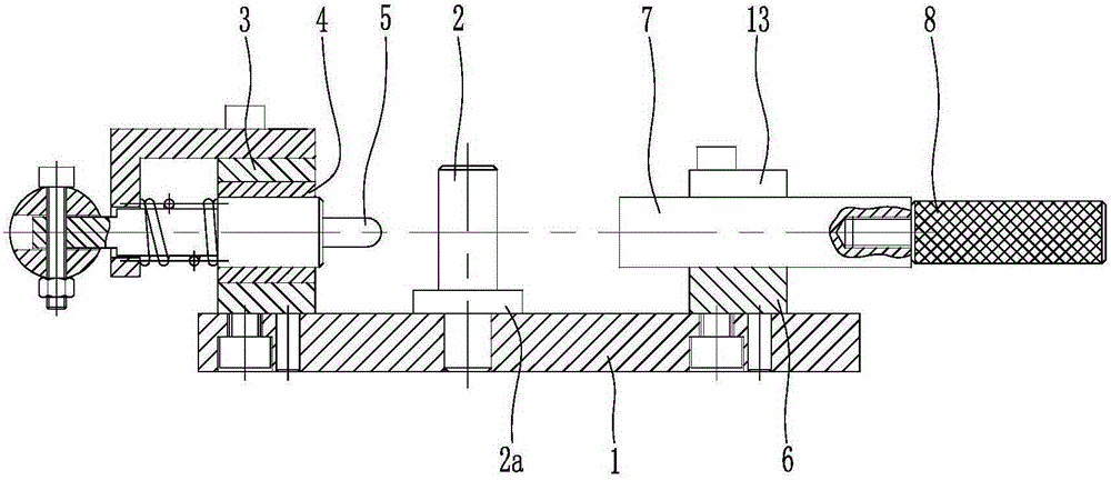
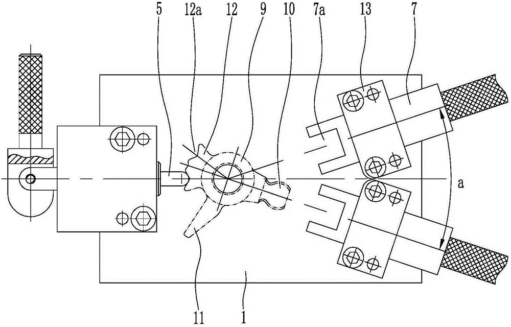
[0018] Below in conjunction with accompanying drawing and embodiment the present invention will be further described:

[0019] like figure 1 , figure 2 As shown, the measuring tool used in the present invention is composed of a base plate 1, a positioning shaft 2, a first support block 3, a bushing 4, a positioning pin 5, a second support block 6, a gauge block 7, a handle 8 and a cover plate 13 and the like. Wherein, the bottom plate 1 is a rectangular flat plate structure, and a positioning shaft 2 is arranged in the middle of the bottom plate 1. The positioning shaft 2 is perpendicular to the bottom plate 1. The top surface of the positioning shaft 2 and the circumferential surface are transitioned through a tapered surface, and the lower end of the positioning shaft 2 extends Inserted into the bottom plate 1, the two are closely matched, and the annular boss 2a integrally formed on the lower part of the positioning shaft 2 is supported by the bottom plate 1.

[0020] li...


PUM


Abstract

The invention discloses a method of detecting ball grooves of a waveform surface of a shift swing rod. A measuring tool comprises a base plate, a positioning shaft, a first supporting block, a lining, a positioning pin, a second supporting block, measuring blocks, and a cover plate. The method comprises the following steps: 1) sleeving the positioning shaft with a spindle sleeve of a shift swing rod, and make the first ball groove of a waveform surface of the shift swing rod face the positioning pin; 2) enabling the right end of the positioning pin to press against the first ball groove of the waveform surface; 3) controlling the first measuring block to move leftwards to check whether a clamping groove in the left end of the first measuring block can clamp a ball head; 4) controlling the positioning pin to loosen the shift swing rod so that the second ball groove of the waveform surface of the shift swing rod faces the positioning pin; 5) enabling the right end of the positioning pin to press against the second ball groove of the waveform surface waveform surface; and 6) controlling the second measuring block to move leftwards to check whether a clamping groove in the left end of the second measuring block can clamp a ball head. The method can detect the positions of the two ball grooves of the waveform surface of the shift swing rod, is simple, fast and labor-saving to operate, and provides an accurate and reliable detection result.

Description

technical field [0001] The invention relates to a method for detecting a ball groove of a wave surface of a shift lever, which is used for detecting the position of the ball groove of the wave surface of an automobile gear lever. Background technique [0002] The shift lever is an important part of the car gearbox. The existing shift lever is generally a steel forging, which is composed of a shaft sleeve, a ball head, a leg and a corrugated surface. There are pin holes, and the female and female pins are passed through the pin holes, so that the bushing and the shaft are fixed. At present, various manufacturers have not specifically tested the position of the ball groove on the wave surface of the shift lever, which may easily lead to poor product quality control and affect the assembly accuracy of the shift lever, making it difficult to meet the requirements of consistent production. Contents of the invention [0003] The technical problem to be solved by the present in...

Claims


Application Information

Patent Timeline
Patent Type & Authority Applications(China)
IPC IPC(8): G01B5/00
Inventor 王絮起
Owner CHONGQING YINGQUAN STANDARD PARTS
Why Eureka
Try Eureka