Particle irradiation device and particle therapy system comprising device
An irradiation device and treatment system technology, applied in the field of cancer treatment devices and systems, can solve problems such as high cost and complex structure of particle therapy systems, and achieve the effect of improving reliability and reducing costs
- Summary
- Abstract
- Description
- Claims
- Application Information
AI Technical Summary
Problems solved by technology
Method used
Image

Examples
Embodiment 1
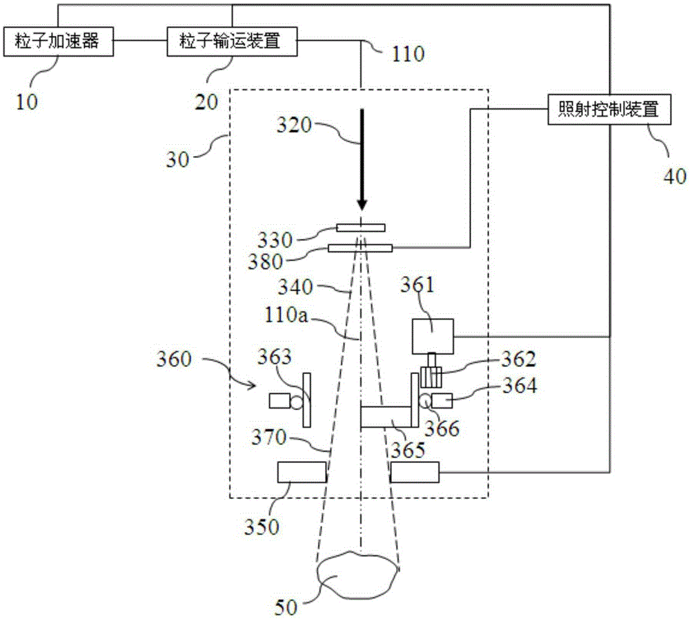
[0032] figure 2 is a schematic diagram of a particle therapy system according to the first preferred embodiment of the present invention, the particle therapy system includes a particle accelerator 10, a particle transport device 20, a particle irradiation device 30, an irradiation control device 40, a patient positioning device, and a tumor target area 50 positioned on the patient positioning device. The particle accelerator 10 , the particle transport device 20 and the particle irradiation device 30 are respectively connected in communication with the irradiation control device 40 to control the particle beam flow. The center of the particle irradiation device 30 and the center of the tumor target area 50 are on the central axis 110a of the particle beam.
[0033] For the convenience of description, the particle beam flow can be artificially divided into the initial particle beam 110 , the first particle beam 320 , the second particle beam 340 and the third particle beam 3...
Embodiment 2
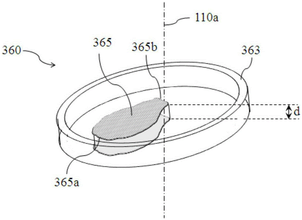
[0046] Same as Embodiment 1, the particle therapy system according to the second embodiment of the present invention includes a particle accelerator, a particle transport device, a particle irradiation device, an irradiation control device and a patient positioning device, on which the tumor target area is positioned. Such as Figure 9 As shown, the particle irradiation device includes a planarization device 360' comprising a rotating member 363' and a shutter 365'. The parts that are the same as those in Embodiment 1 will not be repeated here. The difference from Embodiment 1 is that the outer ring of the rotating member 363' is a gear structure, so as to mesh with the gear of the transmission member for transmission. In addition, according to the requirement of planarization, the shape of the shield 365' is slightly different from that of Embodiment 1.
Embodiment 3
[0048] Same as Embodiment 1, the particle therapy system according to the third embodiment of the present invention includes a particle accelerator, a particle transport device, a particle irradiation device, an irradiation control device, and a patient positioning device. The tumor target area is positioned on the patient positioning device. Such as Figure 10 As shown, the particle irradiation device includes a planarization device 360", and the planarization device 360" includes a driving member 361", a transmission member 362", a rotating member 363" and a shielding member 365". The same part as Embodiment 1 will not be repeated here. The difference from Embodiment 1 is that the transmission member 362" is a belt, so that the driving member 361" drives the rotation of the rotating member 363" by means of the belt. In addition, according to the planarization The shape of the shutter 365" is slightly different from that of Embodiment 1, but the same as that of Embodiment 2. ...
PUM
 Abstract
Description
Claims
Application Information
 - R&D
- Intellectual Property
- Life Sciences
- Materials
- Tech Scout
- Unparalleled Data Quality
- Higher Quality Content
- 60% Fewer Hallucinations
Browse by: Latest US Patents, China's latest patents, Technical Efficacy Thesaurus, Application Domain, Technology Topic, Popular Technical Reports.
© 2025 PatSnap. All rights reserved.Legal|Privacy policy|Modern Slavery Act Transparency Statement|Sitemap|About US| Contact US: help@patsnap.com