Supercharge Your Innovation With Domain-Expert AI Agents!

Pressurized mixing device

A technology of mixing device and mixing chamber, which is applied in mixers, mixing methods, mixers with rotary stirring devices, etc., can solve the problems of complex structure, large volume, poor reliability, etc., and achieve the effect of uniform mixing

Inactive Publication Date: 2016-01-20
四机赛瓦石油钻采设备有限公司
View PDF8 Cites 8 Cited by
  • Summary
  • Abstract
  • Description
  • Claims
  • Application Information

AI Technical Summary

Problems solved by technology

[0002] Traditional sand mixing equipment includes screw auger sand conveyor, mixing tank and sand discharge pump. Traditional equipment has complex structure, large volume, heavy weight, difficult processing, difficult assembly, high manufacturing cost, and poor reliability.

Method used


Image

  • Pressurized mixing device
  • Pressurized mixing device
  • Pressurized mixing device

Examples


Embodiment Construction

[0024] The present invention will be further described below in conjunction with the accompanying drawings and embodiments.

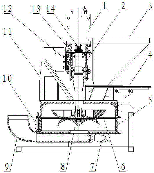
[0025] This embodiment provides a pressurized mixing device, such as figure 1 As shown, it includes a mixing chamber 5, and a stirring shaft 2 that extends into the mixing chamber 5 and is driven by a power source. The bottom of the chamber 5 is connected to the liquid inlet pipe 9, and the lower part of the liquid inlet pipe 9 is provided with a residual liquid discharge port 7. The power source is erected on the mixing chamber 5 through the support structure 11, and the stirring shaft 2 extends vertically into the mixing chamber. 5, in the mixing chamber 5, the thrower body 6 and the stirring impeller 8 are fixed on the stirring shaft 2 in a back-to-back type, the thrower body 6 is on top, and the stirring impeller 8 is on the bottom.

[0026] Further, the stirring shaft 2 is connected to one end of the connecting sleeve 13 through the bearing 14, th...


PUM


Abstract

The invention belongs to the field of oil field fracturing equipment matching and in particular relates to a pressurized mixing device. The device comprises a mixing chamber, and a stirring shaft which stretches into the mixing chamber and is driven by a power source, wherein the upper part of the mixing chamber is communicated with a guide hopper; a liquid outlet is formed in the side wall of the mixing chamber; the bottom of the mixing chamber is communicated with a liquid inlet pipe; a residual liquid outlet is formed in a lower part of the liquid inlet pipe; the power source is erected on the mixing chamber by virtue of a supporting structure; the stirring shaft vertically stretches into the mixing chamber; a thrower body and a mixing impeller are fixed on the stirring shaft in a back-to-back manner in the mixing chamber; and the thrower body is arranged on the upper part, and the mixing impeller is arranged on the lower part. According to the device disclosed by the invention, three functions, such as a screw augur sand conveyer, a mixing tank and a discharge sand pump of the traditional sand mixing equipment, are combined into a whole, and the device is simple in structure, reasonable in design and uniform in fracturing fluid mixing.

Description

technical field [0001] The invention belongs to the supporting field of oilfield fracturing equipment, in particular to a booster mixing device. Background technique [0002] Traditional sand mixing equipment includes screw auger sand conveyor, mixing tank and sand discharge pump. The traditional equipment has complex structure, large volume, heavy weight, difficult processing, difficult assembly, high manufacturing cost, and poor reliability. [0003] In order to enhance the recovery rate of crude oil and better protect the environment of the oil production operation area, the fracturing process is constantly improving and improving, and more optimized sand mixing equipment is needed to help. Contents of the invention [0004] The purpose of the present invention is to overcome the above disadvantages and provide a pressurized mixing device, which integrates the three functions of the traditional sand mixing equipment, such as the screw auger sand conveyor, the mixing tan...

Claims


Application Information

Patent Timeline
IPC IPC(8): B01F13/06B01F7/26B01F15/02B01F3/12B01F27/93
Inventor 余飞梁云张艳
Owner 四机赛瓦石油钻采设备有限公司
Features
  • R&D
  • Intellectual Property
  • Life Sciences
  • Materials
  • Tech Scout
  • Unparalleled Data Quality
  • Higher Quality Content
  • 60% Fewer Hallucinations
Learn More