Eureka AIR delivers breakthrough ideas for toughest innovation challenges, trusted by R&D personnel around the world.

A polyhedron rotary welding tool shared by multiple car bodies

A polyhedron and spin welding technology, applied in auxiliary devices, vehicle parts, manufacturing tools, etc., can solve the problems of increased equipment cost, complex structure, large space occupation, etc., and achieve the effect of short switching cycle, simple operation and small space occupation.

Active Publication Date: 2017-02-01
SHANGHAI DEMEIKE AUTOMOBILE EQUIP MFG
View PDF1 Cites 0 Cited by
  • Summary
  • Abstract
  • Description
  • Claims
  • Application Information

AI Technical Summary

Problems solved by technology

Although the polyhedron rotary welding tool shared by multiple car bodies can be switched quickly, its structure is complex and takes up a lot of space, which increases the cost of equipment

Method used


Image

  • A polyhedron rotary welding tool shared by multiple car bodies
  • A polyhedron rotary welding tool shared by multiple car bodies
  • A polyhedron rotary welding tool shared by multiple car bodies

Examples


Embodiment 1

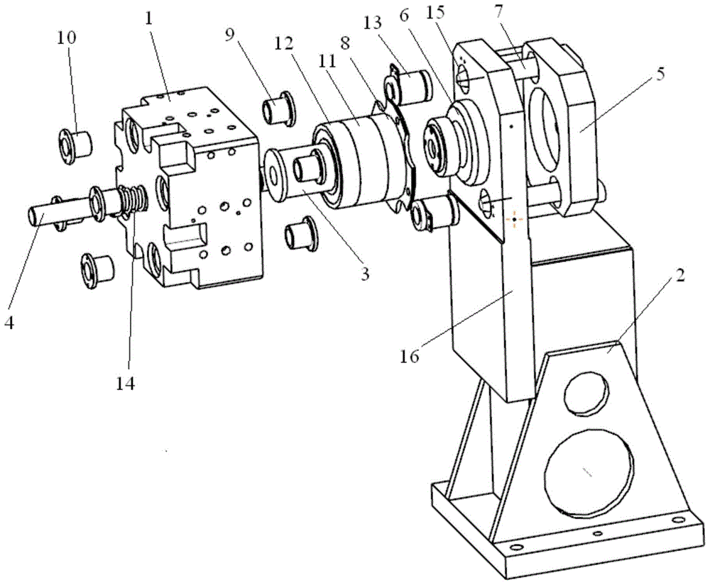
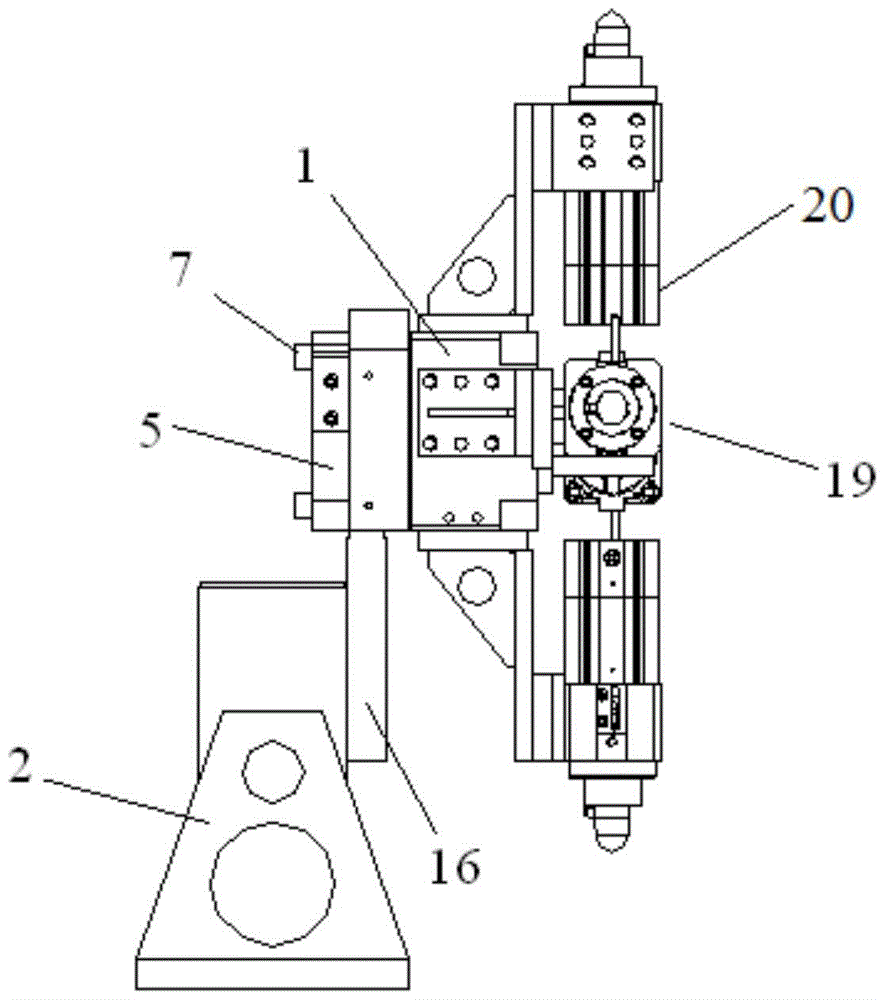
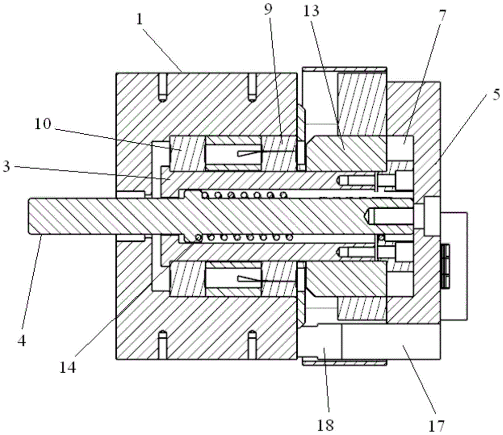
[0029] A polyhedron rotary welding tool shared by multiple car bodies, its structure see figure 1 with figure 2 ,include:

[0030] Mounting base: comprising a fixed seat 2 and a fixed plate 16 arranged on the fixed seat 2, the center of the fixed plate 16 is provided with an internal hollow connecting shaft 6, and the fixed plate 16 is also provided with two first through holes 15, two The first through hole 15 is symmetrically arranged on the fixing plate 16 with the connecting shaft 6 as the center;

[0031] Locking assembly: set on one side of the fixing plate 16, the locking assembly includes a first end cover 5, and the first end cover 5 is provided with a locking pin 7 at a position corresponding to the first through hole 15 on the fixing plate 16 , the lock pin 7 is a tapered lock pin, and the first end cover 5 is also provided with an air supply assembly that promotes the rotation of the polyhedron rotating assembly. The air supply assembly includes an air supply bl...

Embodiment 2

[0036] A polyhedron rotary welding tool shared by multiple car bodies, comprising:

[0037] Mounting base: comprising a fixed seat 2 and a fixed plate 16 arranged on the fixed seat 2, the center of the fixed plate 16 is provided with an internal hollow connecting shaft 6, and the fixed plate 16 is also provided with two first through holes 15, two The first through hole 15 is symmetrically arranged on the fixing plate 16 with the connecting shaft 6 as the center;

[0038] Locking assembly: set on one side of the fixing plate 16, the locking assembly includes a first end cover 5, and the first end cover 5 is provided with a locking pin 7 at a position corresponding to the first through hole 15 on the fixing plate 16 , the lock pin 7 is a tapered lock pin, and the first end cover 5 is also provided with an air supply assembly that promotes the rotation of the polyhedron rotating assembly. The air supply assembly includes an air supply block 17 installed on the first end cover 5 ...


PUM


Abstract

The invention relates to a polyhedron rotation welding tool commonly used for multiple vehicle bodies. The polyhedron rotation welding tool comprises an installation base, a locking assembly and a polyhedron rotation assembly. The polyhedron rotation assembly comprises a rotation polyhedron. Working faces corresponding to four different vehicle types are arranged on the four side faces of the rotation polyhedron respectively. A hollow rotating shaft rotating around the rotation polyhedron and a thrust shaft connected with the locking assembly and pushing the rotation polyhedron to lock or unlock rotation are arranged in the rotation polyhedron. A plurality of second guide sleeves matched with butt joint pins of different vehicle types are arranged on one end face of the rotation polyhedron. The locking assembly is pushed to be loosened through the thrust shaft, then the rotation polyhedron is driven to rotate, the second guide sleeves are in butt joint with the butt joint pins of the corresponding vehicle types, and therefore the working faces of the different vehicle types can be replaced for work. Compared with the prior art, the polyhedron rotation welding tool has the beneficial effects of being small in structure and occupied space, low in cost and the like.

Description

technical field [0001] The invention relates to welding production line equipment in the automobile industry, in particular to a polyhedron rotary welding tool shared by multiple vehicle bodies. Background technique [0002] In the welding production line of an automobile company, at the initial stage of design, the jig for positioning the car body, the skid or the trolley for conveying can basically meet the needs of one or two models of each production line for mixed production. With the development of the automobile market, there are more and more car models, and the replacement cycle is getting shorter and shorter. These changes pose a severe test to the car main engine manufacturers. The original model planning single production method not only has low production efficiency, but also Moreover, the versatility of the equipment is low, which can no longer meet the current development trend of automobile planning. Faced with the production planning of new models, main eng...

Claims


Application Information

Patent Timeline
Patent Type & Authority Patents(China)
IPC IPC(8): B23K37/047
CPCB23K37/047B23K2101/006
Inventor 李海峰刘士亮
Owner SHANGHAI DEMEIKE AUTOMOBILE EQUIP MFG
Why Eureka
Eureka Blog
Learn More