Steel wrapper feed frame device

A technology for feeding racks and ladles, which is applied in the directions of transportation and packaging, thin material handling, winding strips, etc., and can solve the problems of easy stretching of materials, poor lamination accuracy, and high labor intensity.

Inactive Publication Date: 2016-01-20
HAINING RUICHUANG MACHINERY TECH
View PDF6 Cites 2 Cited by
  • Summary
  • Abstract
  • Description
  • Claims
  • Application Information

AI Technical Summary

Problems solved by technology

[0006] The traditional ladle feeding rack device adopts the form of proximity switch for the cloth storage position when it is opened. The material moves up and down with the load roller. It needs manual hand-held materials for lamination, which is labor-intensive and the lamination accuracy is poor

Method used


Image

  • Steel wrapper feed frame device
  • Steel wrapper feed frame device
  • Steel wrapper feed frame device

Examples


Embodiment Construction

[0022] The following are specific embodiments of the present invention and in conjunction with the accompanying drawings, the technical solutions of the present invention are further described, but the present invention is not limited to these embodiments.

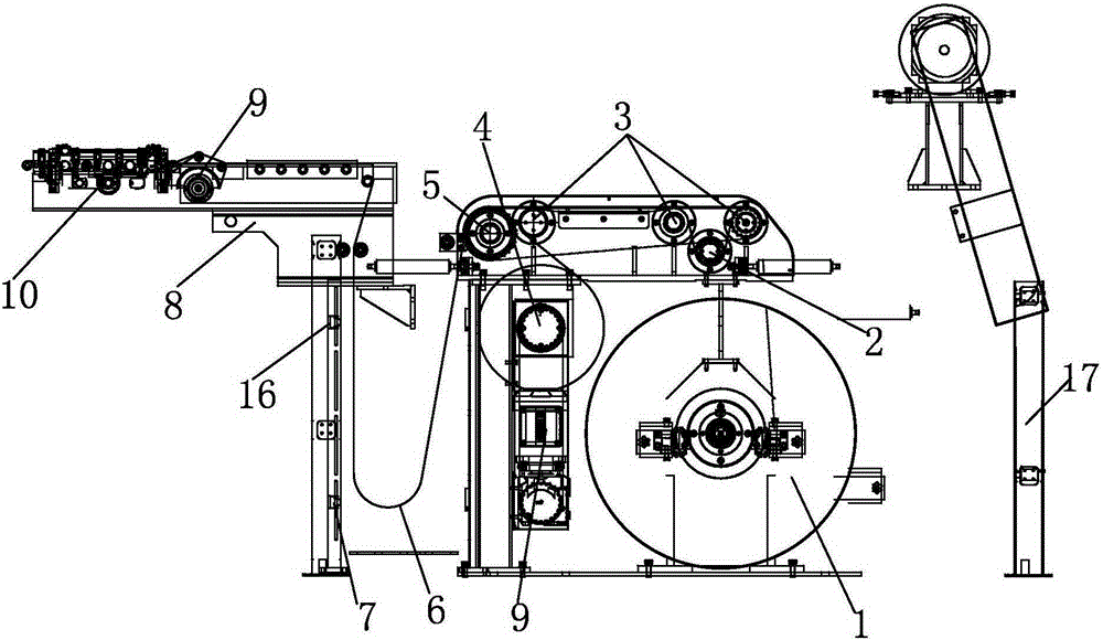
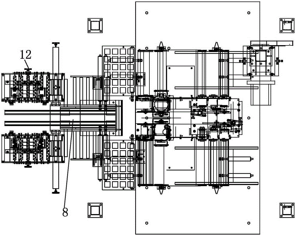
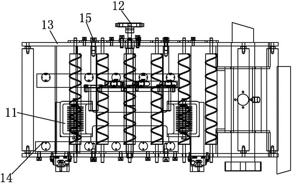
[0023] Such as Figure 1-3 As shown, a ladle feeding rack device includes a material guide mechanism, a material conveying mechanism and a deviation correction mechanism. The material guide mechanism includes an I-shaped wheel 1, and a first support rod is arranged in front of the I-shaped wheel 1, and the I-shaped wheel 1 is provided with a support plate, the end surface of the support plate is provided with the first conveying roller 2 and the second conveying roller 3, and the side of the first support rod close to the I-shaped wheel 1 is provided with a guide motor 9 and a guide motor reducer 4. The material conveying mechanism includes a cloth storage pocket 6, one end of the cloth storage pocket 6 is connected with a...


PUM


Abstract

The invention provides a steel wrapper feed frame device and belongs to the technical field of the production process of tire blanks. By means of the steel wrapper feed frame device, the deficiencies that in the existing steel wrapper feed process, materials are liable to be stretched, an operation is complex, the amount of manual intervention is large, and the attaching precision is low are overcome. The steel wrapper feed frame device comprises a material guiding-distributing mechanism, a material conveying mechanism and a material rectification mechanism. The material guiding-distributing mechanism comprises an I-shaped wheel. A first support rod is arranged in front of the I-shaped wheel. A support plate is arranged above the I-shaped wheel. The upper end face of the I-shaped wheel is provided with a first conveying roller and a second conveying roller. The side, close to the I-shaped wheel, of the support rod is provided with a guiding-distributing motor and a guiding-distributing motor reduction box. The material conveying mechanism comprises a fabric storage bag. One end of the fabric storage bag is connected with a third conveying roller. The third conveying roller is tightly connected with the second conveying roller. The other end of the fabric storage bag is connected with a feed frame. A second support rod is arranged below the feed frame. The fabric storage bag is located between the first support rod and the second support rod. The rectification mechanism is arranged in front of the feed frame.

Description

technical field [0001] The invention belongs to the technical field of tire blank production technology, and relates to a feeding rack device, in particular to a ladle feeding rack device. Background technique [0002] Radial tires came out in the 1940s. Due to the excellent performance brought by its unique structure, after more than half a century of development, the tires have gradually become radial. Radial tires have experienced a long and tortuous development, and now they are becoming more and more flat, tubeless, high-speed, environmentally friendly and functional. With the development of the automobile industry, the performance requirements for tires are getting higher and higher. All-steel radial tires with advantages such as good handling performance, low rolling resistance, fuel saving and good durability and wear resistance have become the main force in the tire industry. However, during the running of all-steel radial tires, cracks and deformations often occur...

Claims


Application Information

Patent Timeline
Patent Type & Authority Applications(China)
IPC IPC(8): B65H41/00B65H23/032B65H20/30
Inventor 刘世鹏
Owner HAINING RUICHUANG MACHINERY TECH
Why Eureka
Try Eureka