Automatic wheel replacing take-up machine

A wire take-up machine and automatic technology, which is applied in the direction of conveying filamentous materials, thin material processing, transportation and packaging, etc., can solve the problems of reducing the service life of the machine, increasing labor intensity, easy rolling and deviation, etc., to achieve extended use Long life, high degree of automation, and the effect of improving work efficiency

Inactive Publication Date: 2016-01-20
王波
View PDF5 Cites 11 Cited by
  • Summary
  • Abstract
  • Description
  • Claims
  • Application Information

AI Technical Summary

Problems solved by technology

[0003] The take-up machine usually includes a conveying device and a winding device. The conveying device is used to transport the I-shaped wheel to the winding device. In the prior art, the I-shaped wheel is placed horizontally during the entire operation process. The I-shaped wheel and the conveyor The contact method is a point contact method. During the conveying process, it is easy to roll and have many problems such as offset, and it is impossible to correctly realize the loading, unloading and winding of the line. The stability is poor, especially when the work needs to turn the I-shaped wheel from the machine. Exporting to other devices requires manual assistance
Heavy workload and increased labor intensity seriously affect work and production efficiency
[0004] Moreover, in the prior art, the empty I-shaped wheel is clamped and fixed by the cylinders facing the top on both sides. The way of free fall directly hits the machine, especially when the large plate, the damage to the machine is particularly obvious
This way of unloading the wheel is easy to cause damage to the machine and reduce the service life of the machine

Method used


Image

  • Automatic wheel replacing take-up machine
  • Automatic wheel replacing take-up machine
  • Automatic wheel replacing take-up machine

Examples


Embodiment Construction

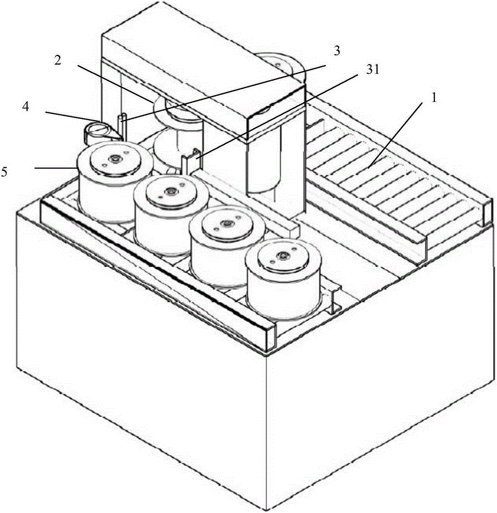
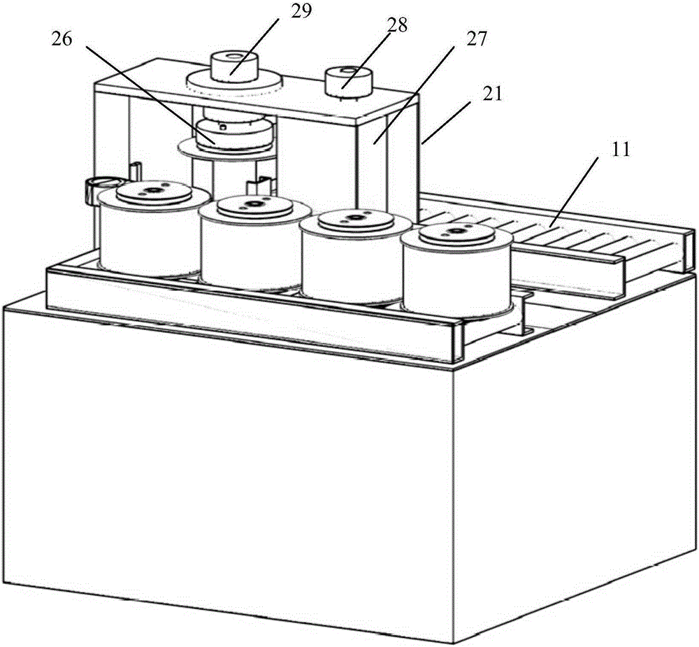
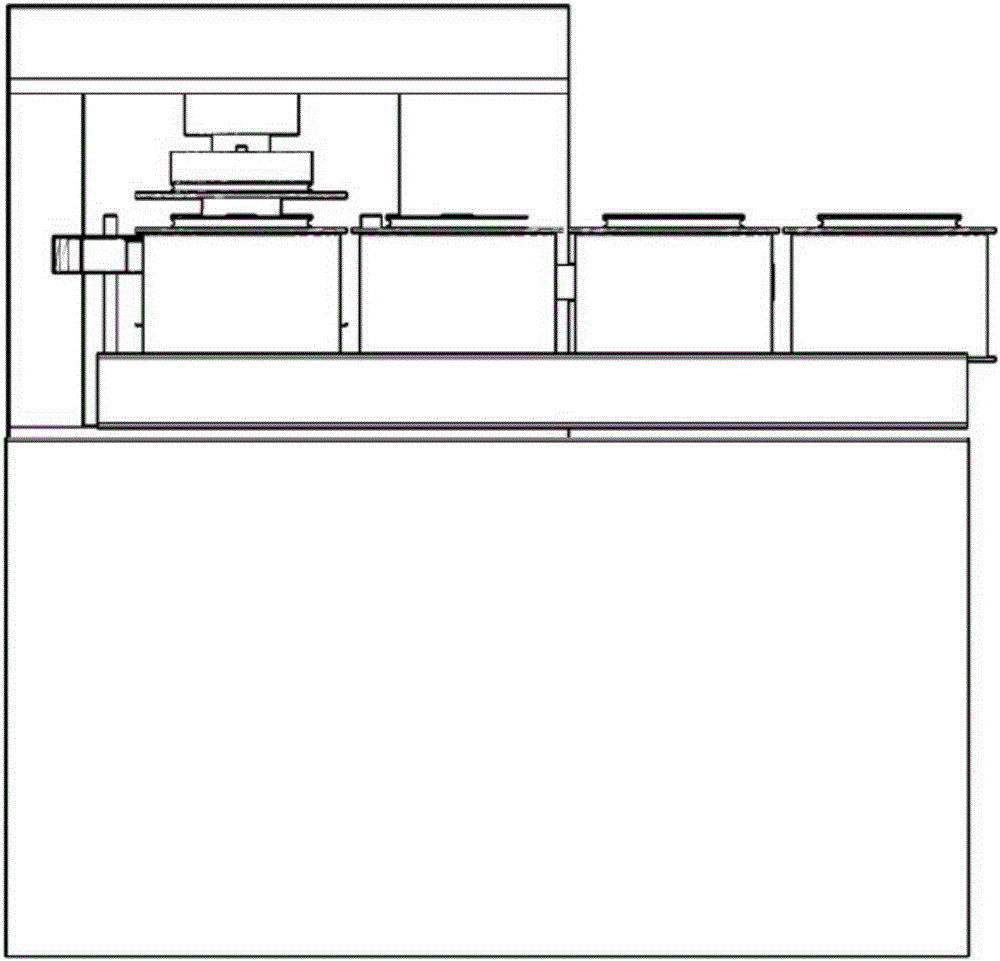
[0032] In the prior art, the I-shaped wheel is placed horizontally during the entire operation process. The contact mode of the I-shaped wheel and the conveyor is a point contact method. It is prone to rolling and offsetting during the conveying process, and the upper wheel cannot be correctly realized. , Unloading the wheel, and taking up the line, the stability is poor, especially when the spool needs to be transferred from the machine to other equipment during the work, it can only be realized with manual assistance. The workload is large and the labor intensity increases, which seriously affects work and production efficiency. Moreover, in the prior art, the empty spools are clamped and fixed by the cylinders with opposite sides. When the spools are fully wound and unloaded, the cylinders on the opposite sides are released at the same time. The damage to the machine is especially obvious when the free fall directly hits the machine, especially when it is on the market. Thi...


PUM


Abstract

The invention discloses an automatic wheel replacing take-up machine which comprises a conveying device and a winding device. I-shaped wheels used for winding are placed vertically, in this way, the problems of rolling, off-tracking and the like during conveying of the I-shaped wheels are solved, and the stability during conveying is improved. According to the automatic wheel replacing take-up machine, an automatic guided vehicle (AGV) can be in seamless butt joint with the conveying device directly, the purposes of automatic wheel mounting, automatic wheel dismounting and transferring are achieved, the workload is reduced, and the working efficiency is improved. By arranging a lifting air cylinder, a lower ejector pin is driven to make the I-shaped wheels to ascend and descend, each I-shaped wheel full of wires can be descended onto the conveying device along with the lower ejector pin, the damage to the machine caused when the I-shaped wheels are dismounted after the I-shaped wheels are full of wires is avoided, the service life of the machine is prolonged, the reliability of the machine is improved, long-term stable operation at an industry scene can be achieved, and automation of the industry is achieved in a real sense. In addition, by arranging a sticking device, a tail wire can be fixed automatically, transportation is convenient, manual participation is not needed in the whole process, and the automation degree is high.

Description

Technical field [0001] The invention belongs to the technical field of wire take-up machines in the metal product industry, and specifically relates to an automatic wheel-changing wire take-up machine. Background technique [0002] The wire take-up machine is used in conjunction with the wire drawing machine to collect the wire after it becomes the ideal wire diameter. The steel bar take-up machine is suitable for the take-up and bundling of cold-drawn steel bars and cold-rolled ribbed steel bars. It can be used with steel bar wire drawing machines, steel bar cold-rolled ribbed machines and steel bar extension machines. [0003] The take-up machine usually includes a conveying device and a winding device. The conveying device is used to convey the spool to the winding device. In the prior art, the spool is placed horizontally during the entire operation. The spool and the conveyor The contact method is a point contact method. It is easy to roll and cause many problems such as offs...

Claims


Application Information

Patent Timeline
Patent Type & Authority Applications(China)
IPC IPC(8): B65H67/06
Inventor 王波
Owner 王波
Why Eureka
Try Eureka