Electric mechanical barring for water turbine

A technology of mechanical discs and water turbines, which is applied in the direction of machines/engines, hydroelectric power generation, mechanical equipment, etc. It can solve the problems of cranking vibration, high installation costs of multiple motors and reducers, and achieve amplified torque, compact structure, and high power. Effect

Active Publication Date: 2016-01-20
保定先奇电力设备技术有限公司
View PDF12 Cites 2 Cited by
  • Summary
  • Abstract
  • Description
  • Claims
  • Application Information

AI Technical Summary

Problems solved by technology

[0004] However, the installation cost of multiple motors and reducers of this kind of cranking finished product is high; if the output speed and power are inconsistent, it will also cause the vibration of the cranking

Method used


Image

  • Electric mechanical barring for water turbine
  • Electric mechanical barring for water turbine
  • Electric mechanical barring for water turbine

Examples


Embodiment 1

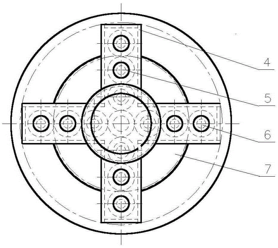
[0040] As above-mentioned mechanical barring, the present embodiment differs from it in that, as figure 2 As shown in the top view of the electromechanical barring of the water turbine of the present invention without the speed reducer, the central gear, the transmission gear 5 and the double gear 6 have the same number of teeth, so that the central gear, the transmission gear 5 and the Only transmission is carried out between the dual gears 6, which plays a simple transmission role, does not change the rotating speed, and its rotating speed is constant; the outer diameter and the number of teeth of the said disc gear 7 are greater than the outer diameter and the number of teeth of the said dual gears 6, In this way, the double gear 6 meshes with the disk gear 7, which not only plays a transmission role, but also increases the transmission ratio. The large gear 7 is decelerated and the disk torque is increased, so that the transmission force is greater.

Embodiment 2

[0042] As above-mentioned mechanical barring, the present embodiment differs from it in that, as figure 2 As shown in the top view of the water turbine of the present invention with electromechanical barring without the reducer, the gear sets are radially evenly divided relative to the chassis, and the included angle between two adjacent groups is 360 / N degrees, so that the output is even.

[0043] Central gear and disk gear 7 have only one.

[0044] A gear set includes at least one transmission gear 5 and a dual gear 6, the dual gear 6 is located at the outermost side of the transmission gear 5, and the number of transmission gears 5 is at least one, which can also be 2, 3, or 4 , 5, 6, 7, 8 or more, the quantity of transmission gear 5 is mainly determined by the weight of the turbine generator shaft and the size of the shaft.

[0045] The number of transmission gears 5 in one gear set is preferably 2-8.

Embodiment 3

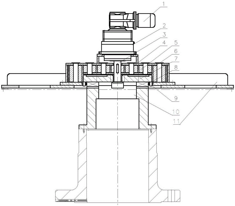
[0047] As mentioned above, the electromechanical barring of the water turbine, the difference of this embodiment is that the disc gear 7 and the connecting cylinder or the connecting plate 10 are clamped together through the meshing mechanism 8, and the meshing mechanism 8 includes a A set of protrusions and a set of corresponding grooves; the cross sections of the protrusions and grooves can be square, circular, or other shapes. The wheel surface of the disc gear 7 is provided with the protrusions or grooves, and the connecting cylinder or the connection plate 10 is provided with the grooves or protrusions; the protrusions are inserted into the grooves and locked, and when clamped There is a gap between the protrusion and the groove, and they are not in contact.

[0048] The purpose of barring is to verify whether the turbine shaft and generator shaft are installed in the center position. If the turbine shaft and generator shaft are installed in the center position, there wil...


PUM


Abstract

The invention discloses an electric mechanical barring for a water turbine. The electric mechanical barring comprises an electromotor, a reduction box and a gear transmission mechanism used for transmitting the output of the reduction box. The gear transmission mechanism comprises a sun gear, gear sets and a shaft turning gear. The sun gear is engaged with the N gear sets. Each gear set comprises a duplicate gear and at least one transmission gear. Each transmission gear is externally engaged with the sun gear. Each duplicate gear is located at the outermost end of the corresponding transmission gear. The upper half portion of the duplicate gear is engaged with the corresponding transmission gear, and the lower half portion of the duplicate gear is engaged with the shaft turning gear. The shaft turning gear is located at the lower end of the sun gear and is coaxial with the sun gear. The shaft turning gear is engaged with the N duplicate gears and is in clearance fit with an output shaft. The N is an integer greater than 1. Accordingly, the cost is low; the structure is impact; the shake of the barring caused by the inconsistence of the rotating speed and the power is avoided; the installation is simple and convenient.

Description

technical field [0001] The invention relates to the technical field of mechanical barring, in particular to an electromechanical barring for a water turbine. Background technique [0002] In the installation of the new unit of the current hydropower station and the overhaul of the old unit, errors will inevitably occur during the installation and overhaul of the unit, which will cause the axis of the unit to incline to varying degrees. And the level of the axis and the mirror plate has been preliminarily adjusted, and under the condition that the force of each tile of the thrust bearing is relatively uniform, the unit is turned to facilitate the measurement of the guide bearing, flange, collector ring, etc. to check the inclination of the axis Whether the degree meets the requirements and adjust in time. [0003] Application No. 02135704's invention "Elastic Force Couple Turning Device" discloses a special tool for vertical hydraulic generator sets and other rotating equipm...

Claims


Application Information

Patent Timeline
IPC IPC(8): F03B11/00
CPCY02E10/20
Inventor 郭泉生
Owner 保定先奇电力设备技术有限公司
Why Eureka
Try Eureka