
Ultrahigh-pressure stop valve

A cut-off valve, ultra-high pressure technology, applied in the direction of valve lift, valve details, valve device, etc., can solve the problems of unreasonable ball head seal cut-off, no anti-rotation structure, large force on the valve stem, etc., to improve sealing reliability , improve service life, good pressure bearing performance

Inactive Publication Date: 2016-01-20
SHANGHAI INST OF MEASUREMENT & TESTING TECH
View PDF13 Cites 6 Cited by
  • Summary
  • Abstract
  • Description
  • Claims
  • Application Information

AI Technical Summary

Problems solved by technology

[0006] D1 does not have an anti-rotation structure that restricts the rotation of the valve needle, and cannot guarantee that the valve needle does not rotate slightly during the up and down linear motion; D2 uses a principle similar to a sliding screw pair to ensure the up and down linear motion of the valve needle, through the valve stem Nut 3, pin 14, stop bolt 4, limit washer 5, and screw 6 limit the position of the lower valve stem 2. The structure is relatively complicated, and it is not suitable for the operation of the valve in an ultra-high pressure environment; D3 not only does not limit the valve needle Rotation anti-rotation structure, and for high pressure and ultra-high pressure measurement above 100MPa, in order to realize the cut-off of the pipeline, the ball head seal cut-off in D3 is unreasonable, although the ball head seal can provide The flow rate of the pipeline is relatively large, but the force on the valve stem is too large, which is not suitable for the operation of the valve. Therefore, the ball head structure of D3 is not suitable for use in ultra-high pressure environments
[0007] Secondly, under the ultra-high pressure environment, not only the tip of the valve needle is under great pressure, but also the stem of the valve needle itself is under great pressure, although the three valves disclosed in D1, D2 and D3 all use similar sealing rings or sealing packing structure, but the shape of the sealing ring or sealing packing cannot better realize the dynamic sealing of the valve needle rod in the ultra-high pressure environment, which is not conducive to the work of the valve needle rod in the ultra-high pressure environment

Method used


Image

  • Ultrahigh-pressure stop valve
  • Ultrahigh-pressure stop valve
  • Ultrahigh-pressure stop valve

Examples


Embodiment Construction

[0044] The present invention will be further described below in conjunction with accompanying drawing.

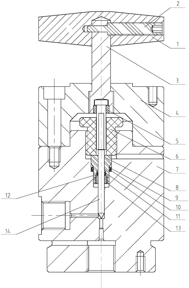
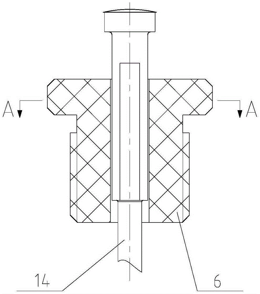
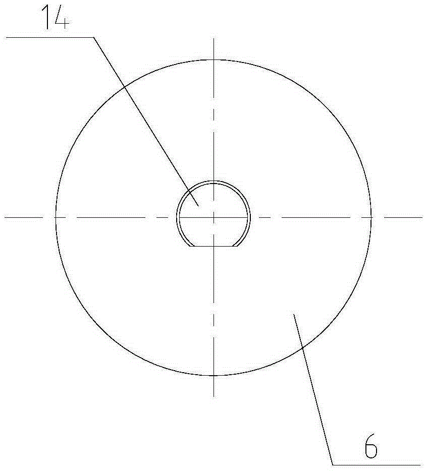
[0045] Such as figure 1 As shown, as a preferred embodiment of the present invention, the stop valve includes a handle 1, a handle pin 2, a valve stem 3, a valve body, a stop nut 5, a compression nut 6, a valve seat 8, and a first extended metal sealing ring 9 , The first wear-resistant hard fiber seal ring 10, the second extended metal seal ring 11, the second wear-resistant hard fiber seal ring 12, the lock nut 13 and the valve needle 14.

[0046] The handle 1 and the upper end of the valve stem 3 are vertically crossed and fixed by the handle pin 2 .

[0047] For the convenience of processing and assembly, the valve body consists of upper and lower parts, including upper valve body 4 and lower valve body 7 . The valve body is made of stainless steel, which has obtained very high strength and toughness through solution treatment, and can withstand high pressure. The up...


PUM


Abstract

An ultrahigh-pressure stop valve comprises a handle, a valve rod, a valve body, a gland nut and a valve needle. An axial through hole is formed in the gland nut vertically fixed into the valve body, and the valve needle is movably sleeved with the through hole; and a limiting face for preventing the valve needle from rotating around the axis direction is arranged on the matched segment of the valve needle and the through hole of the gland nut. A mounting hole is formed in the position, below the gland nut, in the valve body, and a valve seat is vertically arranged in the mounting hole; a first sealing cavity which is narrow in upper portion and wide in lower portion is formed between the valve seat and the mounting hole; a first extending metal seal ring and a first wear-resisting hard fiber sealing ring are arranged in the lower end of the first sealing cavity in a vertically-stacked manner; the valve needle movably penetrates a central through hole of the valve seat, and a second sealing cavity which is narrow in upper portion and wide in lower portion is arranged between the outer circumferential face of the valve needle and the inner circumferential face of the central through hole; and a second extending metal seal ring and a second wear-resisting hard fiber sealing ring are arranged in the lower end of the second sealing cavity in a vertically-stacked manner. The sealing performance of the valve needle under the high-pressure environment and the ultrahigh environment can be ensured, the service life of the valve is prolonged, and the sealing reliability of the valve is improved.

Description

technical field [0001] The invention relates to the field of pressure measurement, in particular to an ultra-high pressure cut-off valve. Background technique [0002] The pressure range involved in pressure measurement is from a few Pa to more than 2000 MPa, which is usually divided into micro pressure (<10kPa), low pressure (0.01MPa~0.25MPa), medium pressure (0.25MPa~100MPa), high pressure (>100MPa) , Ultra-high pressure (>600MPa). The medium for transmitting pressure mainly includes gas, liquid and other fluids. For high pressure and ultra-high pressure measurement, the generation and measurement of pressure must be involved; generally, the liquid medium is pressurized to the required ultra-high pressure through pressure pipes, valves, and power sources, and then the value is reproduced by the standard source. High-pressure pressure measurement is very critical, and its safety and sealing are important factors to ensure accurate transmission of pressure values....

Claims


Application Information

Patent Timeline
Patent Type & Authority Applications(China)
IPC IPC(8): F16K1/00F16K1/38F16K1/48F16K1/32F16K1/50F16K27/02F16K41/06
CPCF16K1/00F16K1/32F16K1/38F16K1/487F16K1/50F16K27/0254F16K41/06
Inventor 洪扁潘征宇胡安伦张忠立任学弟胡玲周毅冰
Owner SHANGHAI INST OF MEASUREMENT & TESTING TECH
Learn More