
Solar intelligent LED lamp

An LED lamp, solar energy technology, applied in directions with built-in power supply, lighting auxiliary devices, lighting and heating equipment, etc., can solve problems such as affecting user experience, poor signal reception performance, and unreasonable structural design of intelligent lamps, etc. Improve antenna communication quality, enhance antenna performance, and increase user experience

Active Publication Date: 2016-01-20
SHENZHEN CENTURY SUNSHINE LIGHTING
View PDF3 Cites 7 Cited by
  • Summary
  • Abstract
  • Description
  • Claims
  • Application Information

AI Technical Summary

Problems solved by technology

[0002] For example, the patent of publication number: CN204254342U discloses a kind of LED intelligent lamp. More and more lamps are realized by intelligent control. Smart home has become the mainstream of current lamps. The performance of receiving signals is poor, so it directly affects the user experience; if it is necessary to improve the signal receiving and transmitting performance of LED lamps, the key lies in whether the antenna it sets can have excellent performance. If a good router configuration antenna should It has strong gain and other electrical properties; at present, smart homes usually use 2.4G frequency band and 5G frequency band as the network frequency selection of WIFI, so the antenna has better electrical performance on the two frequency bands. A Bigger Challenge for Home Signal Acceptance

Method used


Image

  • Solar intelligent LED lamp
  • Solar intelligent LED lamp
  • Solar intelligent LED lamp

Examples


Embodiment 2

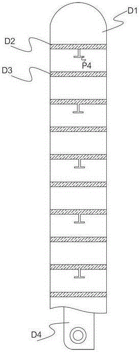
[0046] Assuming that the number of notches K8 is N, the length of the third radiating arm K7 is Lmm, and the radius of the annular radiating arm K5 is Kmm, then K=L / N. Through many tests, it is found that if the above specifications are met, the performance of the antenna will be more optimized, especially in terms of return loss, the return loss of the return loss in the 2.4-2.48GHz frequency band and 5.15-5.875GHz frequency band is better than -17dB .

Embodiment 3

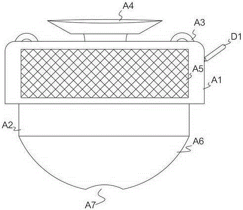
[0048] According to the solar smart LED lamp described in this embodiment, the number of the cutout holes K8 is six. Wherein, the corners of the triangle arms K1 are rounded. Wherein, the ring arm K1 is an equilateral triangle, and the length of the inner side of the ring arm K1 is 20mm. Wherein, the distance between the capacitive coupling dipole arm P4 and the PCB board P1 is 15mm. Wherein, the outer edge of the ring arm K1 is a zigzag edge. Wherein, the bottom of the LED lens A6 is also provided with a concave arc A7 for uniform light; through the above configuration, the gain of the antenna is higher, the isolation is better, and the standing wave ratio performance is also better.

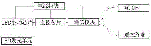
[0049] A solar smart LED lamp described in this embodiment also includes a solar battery panel A5 attached to the outer wall of the upper casing A1, and the solar battery panel A5 is connected to the power module; the battery panel is used to supplement the power module permanent power suppl...


PUM


Abstract

The invention discloses a solar intelligent LED lamp. The solar intelligent LED lamp comprises an upper housing and a lower housing, wherein an LED lens is arranged at the bottom of the lower housing; an LED lighting unit is arranged in the lower housing; a control circuit device used for controlling the LED lighting unit to turn on and off is arranged in the upper housing; the control circuit device comprises a main control chip, a communication module, an LED driving chip and a power supply module; the LED driving chip is electrically connected with the LED lighting unit and is used for driving the LED lighting unit; the power supply module is electrically connected with the main control chip, the communication module and the LED driving chip respectively; an antenna is pivotally connected to the outer wall of the upper housing. Through the solar intelligent LED lamp, the antenna is arranged at the outer wall of the lamp housing, so that the communication quality of the antenna is improved; the interior structure of the antenna is improved, so that the antenna performance is improved, and the user experience of the LED lamp is improved.

Description

technical field [0001] The invention relates to a solar intelligent LED lamp. Background technique [0002] For example, the patent of publication number: CN204254342U discloses a kind of LED smart lamp. More and more lamps are realized by intelligent control. Smart home has become the mainstream of current lamps. The performance of receiving signals is poor, which directly affects the user experience; if it is necessary to improve the performance of signal reception and transmission of LED lamps, the key lies in whether the antenna it sets can have excellent performance. If a good router configuration antenna should It has strong gain and other electrical properties; at present, smart homes usually use 2.4G frequency band and 5G frequency band as the network frequency selection of WIFI, so the antenna has better electrical performance on the two frequency bands. One of the biggest challenges for home signal acceptance. Contents of the invention [0003] The purpose of t...

Claims


Application Information

Patent Timeline
IPC IPC(8): F21S9/03F21V23/00F21V23/04F21V21/092F21Y115/10
CPCF21S9/037F21V21/092F21V23/003F21V23/04
Inventor 欧志洪
Owner SHENZHEN CENTURY SUNSHINE LIGHTING
Features
  • Generate Ideas
  • Intellectual Property
  • Life Sciences
  • Materials
  • Tech Scout
  • Unparalleled Data Quality
  • Higher Quality Content
  • 60% Fewer Hallucinations
Learn More