
Fuel storage tank for nuclear power plant spent fuel dry-type storage

A technology for spent fuel and nuclear power plants, which is applied in the field of dry storage of spent fuel in nuclear power plants, can solve the problems that operators are exposed to large radiation doses, the fuel storage tanks cannot be reused, and the welding grooves are difficult to process, so as to achieve the realization of reuse. , Fast loading and retrieval, ensuring the effect of sealing performance

Active Publication Date: 2016-01-20
CHINA NUCLEAR POWER DESIGN COMPANY +3
View PDF5 Cites 12 Cited by
  • Summary
  • Abstract
  • Description
  • Claims
  • Application Information

AI Technical Summary

Problems solved by technology

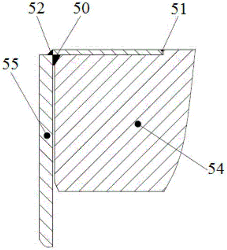
[0004] Although sealing the fuel storage tank by welding can achieve good sealing performance, there are still the following three major problems: 1) After the fuel storage tank is loaded with spent fuel assemblies, the top cover 54 and the barrel 55 need to be welded, and personnel The radiation dose received when welding the top cover 54 is relatively large; 2) After the fuel storage tank is stored in the concrete silo for a certain number of years, it is necessary to reprocess the spent fuel assembly. At this time, it is necessary to use a special cutting tool to clean the fuel storage tank The spent fuel assembly can only be retrieved after the top cover 54 is removed, and the cutting operation will also cause the operator to bear a large radiation dose; 3) After the fuel storage tank is cut, due to the local structure of the welding part At the same time, it has a certain degree of radioactivity, so that it is difficult to reprocess the welding groove, so the fuel storage tank cannot be reused, and it can only be treated as radioactive waste after it is used once.

Method used


Image

  • Fuel storage tank for nuclear power plant spent fuel dry-type storage
  • Fuel storage tank for nuclear power plant spent fuel dry-type storage
  • Fuel storage tank for nuclear power plant spent fuel dry-type storage

Examples


Embodiment Construction

[0041] In order to make the purpose, technical solution and beneficial technical effects of the present invention clearer, the present invention will be further described in detail below in conjunction with the accompanying drawings and specific embodiments. It should be understood that the specific implementations described in this specification are only for explaining the present invention, not for limiting the present invention.

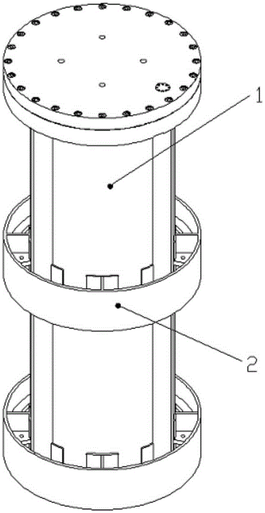
[0042] see figure 2 , The fuel storage tank for dry storage of spent fuel in a nuclear power plant in the present invention is a flanged fuel storage tank, which includes a storage tank body 1 and a storage tank support structure 2 . Wherein, the storage tank body 1 is a cylindrical container with a flange top cover, which bears a certain pressure inside and functions to contain radioactive substances. The storage tank support structure 2 is spliced ​​by steel plates, which is welded and fixed on the periphery of the storage tank body 1, and pro...


PUM


Abstract

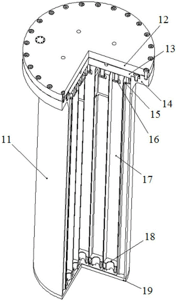
The invention discloses a fuel storage tank for nuclear power plant spent fuel dry-type storage. The fuel storage tank comprises a storage tank body and a storage tank support structure fixed at the periphery of the storage tank body. The storage tank body comprises a cylinder, an outer top cover, an inner top cover, a flange and a base plate. The base plate is fixedly connected at the bottom of the cylinder. The flange is fixedly connected at the top of the cylinder. The top of the flange is equipped with a step sealing surface. The inner top cover and the outer top cover are connected with different steps of the step sealing surface of the flange through bolts. Compared with the prior art, the fuel storage tank employs a flange-type top cover structure, thus the fuel storage tank top cover sealing performance is ensured, and the sealing operation difficulty is lowered. A spent fuel assembly can be loaded and taken out and recycle of the fuel storage tank can be achieved.

Description

technical field [0001] The invention relates to the field of nuclear power plant spent fuel dry storage, and more specifically, the invention relates to a fuel storage tank for spent fuel dry storage. Background technique [0002] At present, the mainstream dry storage scheme for spent fuel in the world is the concrete silo storage scheme, and its basic container includes two fuel storage tanks and concrete silos. Among them, the fuel storage tank is used to load spent fuel components and contain radioactivity. It is generally a steel sealed container filled with a certain pressure of inert gas to provide an inert storage environment for spent fuel components; concrete silos are used to store fuel storage tanks , provide the function of shielding and physical isolation, and conduct the heat release inside the fuel storage tank in a passive way. [0003] The main functions of the fuel storage tank are: 1) providing a seal to contain radioactive substances; 2) providing struc...

Claims


Application Information

Patent Timeline
Patent Type & Authority Applications(China)
IPC IPC(8): G21C19/06
CPCY02E30/30
Inventor 王鑫段远刚高景辉罗志远李晓蔚唐邵华杨锦春周智慧潘跃龙李超联刘翠波张学岭刘彦章蒋华杨寿海袁呈煜唐琼辉欧国勇左永德
Owner CHINA NUCLEAR POWER DESIGN COMPANY
Learn More