Lightweight RF Connectors

A radio frequency connector, light-weight technology, applied in the direction of connection, two-part connection device, electrical components, etc., can solve problems such as unsatisfactory, small distance between low-profile antenna unit and reflector, and connector without strength performance, etc., to achieve reduction Effects of chain breaking, increased strength, and reduced weight

Active Publication Date: 2018-01-02
中国电子科技集团公司第四十研究所
View PDF5 Cites 0 Cited by
  • Summary
  • Abstract
  • Description
  • Claims
  • Application Information

AI Technical Summary

Problems solved by technology

[0002] With the development of science and technology, military electronic equipment is becoming more and more miniaturized, integrated and modularized. The distance between the low-profile antenna unit and the reflector of the latest blind-supplying radar in my country is small, and the connector needs to realize the connection between the antenna unit and the feeder. The connection of the radio frequency signal of the system should also become the bearing substrate of the antenna transmitting surface; in the prior art, the connector cannot meet the requirements of strength performance, and cannot be applied to the radio frequency channel with severe stress environment or strict weight reduction requirements. At this stage, the latest national equipment, especially the requirements of airborne and spaceborne equipment, conventional RF coaxial connectors cannot meet the installation requirements of this new type of advanced complete machine

Method used


Image

  • Lightweight RF Connectors
  • Lightweight RF Connectors
  • Lightweight RF Connectors

Examples


Embodiment 1

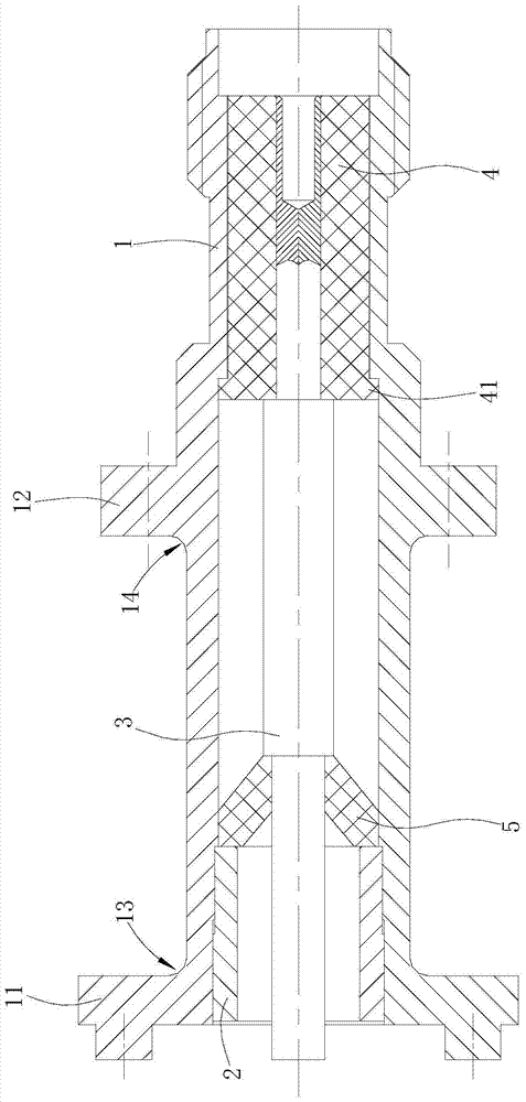
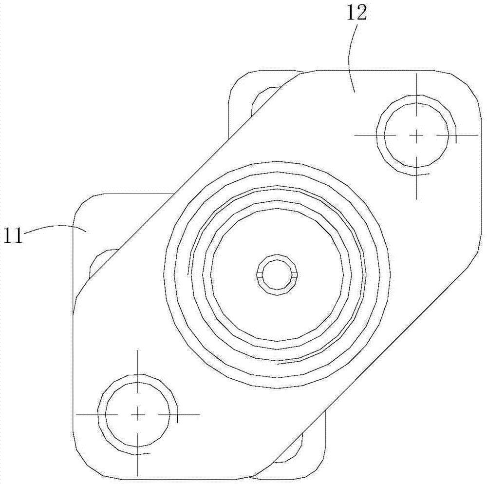
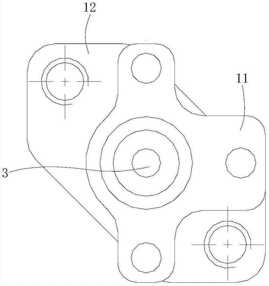
[0022] like Figures 1 to 5 shown

[0023] The lightweight radio frequency connector includes an inner conductor 3, a shell 1, a pressing sleeve 2 and two insulating sleeves.

[0024] The shell 1 is in the shape of a straight tube, the rear end of the outer wall of the shell 1 extends outwards with a first flange 11, the first flange 11 is a special-shaped flange, and a process fillet 13 is provided between the front end of the first flange 11 and the outer wall of the shell 1 There is a second flange 12 extending outward from the middle of the outer wall of the housing 1, and a process fillet 14 is also provided between the rear end surface of the second flange 12 and the outer wall of the housing 1. The second flange 12 is a diamond-shaped flange with two holes. The distance from the flange 12 to the rear end of the housing 1 is assumed to be L, the distance of L is 80mm, the length of the housing 1 is assumed to be H, and the length of H is 146mm, satisfying the following ...

Embodiment 2

[0041] The difference between this embodiment and the first embodiment is only that the distance of L can be 90mm, the length of H can be 140mm, and L:H=4.5:7.0.

Embodiment 3

[0043] The difference between this embodiment and the first embodiment is only that the distance of L can be 84mm, the length of H can be 144mm, and L:H=4.2:7.2.


PUM


Abstract

The present invention provides a light-weight radio frequency connector, which includes an inner conductor, a housing, a pressing sleeve and at least one insulating sleeve, the insulating sleeve and the pressing sleeve are both sleeved in the housing, and the inner conductor is sleeved in the insulating sleeve; The shell is in the shape of a straight tube, the rear end of the outer wall of the shell is fixedly connected with a first flange, and the middle part of the outer wall of the shell is fixedly connected with a second flange. According to the requirements of the use environment and simple and reliable design ideas, the overall structural design of the connector is carried out. Its main structural parts are composed of a shell, a press sleeve, an insulator, and an inner conductor. Press-fitting fixes the insulator in the shell, and the structure has the characteristics of simple reliability and good fixation. Moreover, the lightweight RF connector is fixed by two flanges. Compared with the technical problem that the connector in the prior art is prone to breakage in harsh stress environments, the strength of the lightweight RF connector is enhanced and the cost is reduced. The broken link when using high-quality RF connectors.

Description

technical field [0001] The invention relates to a radio frequency connector, in particular to a lightweight radio frequency connector. Background technique [0002] With the development of science and technology, military electronic equipment is becoming more and more miniaturized, integrated and modularized. The distance between the low-profile antenna unit and the reflector of the latest blind-supplying radar in my country is small, and the connector needs to realize the connection between the antenna unit and the feeder. The connection of the radio frequency signal of the system should also become the bearing substrate of the antenna transmitting surface; in the prior art, the connector cannot meet the requirements of strength performance, and cannot be applied to the radio frequency channel with severe stress environment or strict weight reduction requirements. At this stage, the latest national equipment, especially the requirements of airborne and spaceborne equipment, c...

Claims


Application Information

Patent Timeline
Patent Type & Authority Patents(China)
IPC IPC(8): H01R13/46H01R24/40
Inventor 张宿柏雪崧周大敏陈侃周荣景余珺
Owner 中国电子科技集团公司第四十研究所
Why Eureka
Try Eureka