A high-voltage connector

A technology of high-voltage connectors and connecting seats, which is applied in the direction of connection, installation of connection parts, and parts of connection devices, etc. It can solve problems such as high single-circuit working voltage, easy shrinkage of materials, and difficulty in meeting withstand voltage requirements.

Active Publication Date: 2016-01-20
中国电子科技集团公司第四十研究所
View PDF5 Cites 7 Cited by
  • Summary
  • Abstract
  • Description
  • Claims
  • Application Information

AI Technical Summary

Problems solved by technology

[0002] At present, high-voltage connectors include plugs and sockets. When in use, the plugs and sockets are mated and connected to realize the connection between various components. However, ordinary high-voltage connectors have the following disadvantages: 1. Due to the large number of product cores and single-circuit operating voltage High, it is difficult to meet the withstand voltage requirement of 35kVd.c.; 2. An air gap is easy to form at the mating interface of the plug and the socket, especially when the product is used in an airborne environment at an altitude of 21,000 meters, the air pressure is low, The temperature is low (4.4kPa, -55°C). Under the condition of low temperature and low pressure, the material is easy to shrink, and the air is more likely to break down. If the mating interface is not well sealed, the air between the interfaces is easy to form a "surface flashover". Resulting in breakdown failure; 3. After ordinary high-voltage connectors and high-voltage wires are welded, they must be potted to ensure good sealing
However, it is difficult to guarantee a good seal between the potting compound and the product (tail sleeve, high-voltage wire)

Method used


Image

  • A high-voltage connector
  • A high-voltage connector
  • A high-voltage connector

Examples


Embodiment Construction

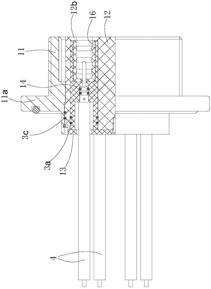
[0032] like Figures 1 to 7 shown

[0033] This high voltage connector consists of a plug and a socket.

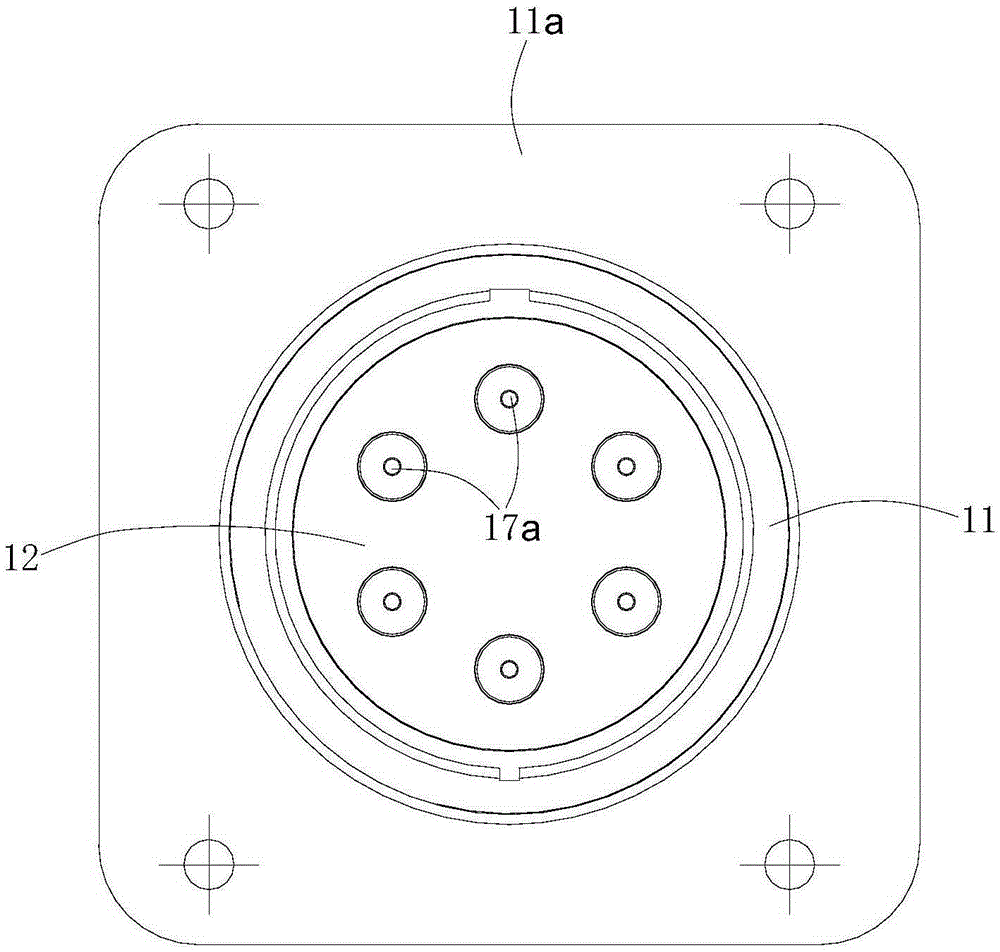
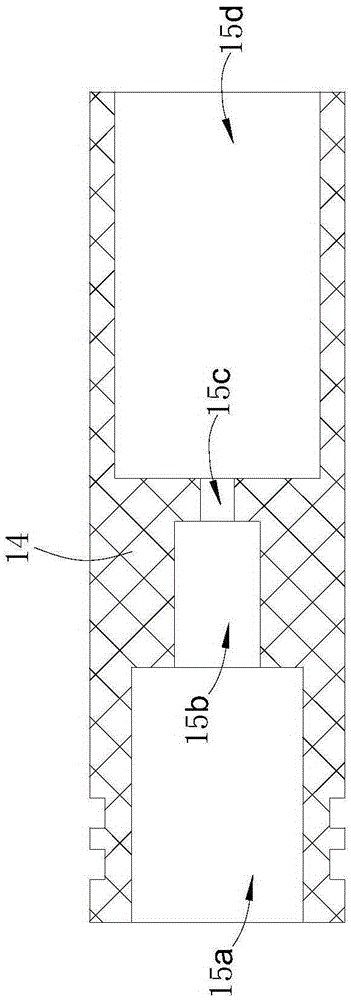
[0034] The socket includes a socket housing 11, a socket mounting plate 12, a socket pressing plate 13, a sealing sleeve 16, six groups of pin assemblies, six socket insulating sleeves 14 and a plurality of sealing rings.

[0035] The socket mounting plate 12 is set in the socket housing 11. The rear part of the socket housing 11 is provided with external threads, and the outer side of the middle part of the socket housing 11 is provided with a flange 11a. Two third sealing rings 3c are provided, the rear end face of the socket mounting plate 12 is a plane, and the socket mounting plate 12 has six first mounting holes (not shown in the figure), and the first mounting holes run through the socket mounting plate 12 On the front and rear end faces, the front end of the first installation hole wall extends inwardly with an inner convex ring 12b, the front side of the socket ...


PUM


Abstract

The invention brings forward a high-voltage connector comprising a plug and a socket. A socket casing sleeves a socket installing plate of the socket. First installing holes are arranged in the socket installing plate. The front side of the socket installing plate is fixed with a socket pressure plate. Each pin assembly comprises a pin portion and a pin connecting seat. Socket insulating tube sleeves are installed in the first installing holes. A step hole is arranged in each socket insulating tube sleeve. Sealing rings are arranged between the pin connecting seat and hole walls of the step holes. A plug installing plate of the plug is provided with second installing holes. The rear side of the plug installing plate is fixed with a plug pressure plate. Jack assemblies are arranged in the second installing holes. Each jack assembly comprises a jack connecting seat and a jack portion. A plug insulating tube sleeve is installed in each second installing hole. Step holes are arranged in the plug insulating tube sleeves. The jack assemblies are installed in the step holes. The high-voltage connector is used for connection and transmission of high-voltage signals in a radar system, and mainly aims to solve problems of stable transmission of the high-voltage signals. An interface seal structure is employed to guarantee stable transmission of multi-path high-voltage signals.

Description

technical field [0001] The invention relates to a high-voltage connector. Background technique [0002] At present, high-voltage connectors include plugs and sockets. When in use, the plugs and sockets are mated and connected to realize the connection between various components. However, ordinary high-voltage connectors have the following disadvantages: 1. Due to the large number of product cores and single-circuit operating voltage High, it is difficult to meet the withstand voltage requirement of 35kVd.c.; 2. An air gap is easy to form at the mating interface of the plug and the socket, especially when the product is used in an airborne environment at an altitude of 21,000 meters, the air pressure is low, The temperature is low (4.4kPa, -55°C). Under the condition of low temperature and low pressure, the material is easy to shrink, and the air is more likely to break down. If the mating interface is not well sealed, the air between the interfaces is easy to form a "surface...

Claims


Application Information

Patent Timeline
Patent Type & Authority Applications(China)
IPC IPC(8): H01R13/52H01R13/622H01R13/73H01R13/533
Inventor 刘敏郭庆领余海洋彭长江
Owner 中国电子科技集团公司第四十研究所
Why Eureka
Try Eureka