Mounting structure of photovoltaic power generation system

A technology of photovoltaic power generation system and installation structure, applied in photovoltaic power generation, support structure of photovoltaic modules, photovoltaic modules, etc., can solve the problems of one-way connection, complex structure of connectors, low reliability, etc., to improve installation efficiency, The effect of simple structure and convenient operation

Inactive Publication Date: 2016-01-20
VERSOLSOLAR HANGZHOU
View PDF6 Cites 1 Cited by
  • Summary
  • Abstract
  • Description
  • Claims
  • Application Information

AI Technical Summary

Problems solved by technology

[0003] The invention provides an installation structure of a photovoltaic power generation system that is simple in structure, easy to install, and has good firmness and high reliability after the components are spliced ​​together, and can realize horizontal and vertical two-way connections according to the size of the site; solves the problem The connectors in the prior art have complex structures, low reliability, and only one-way connections can be realized

Method used


Image

  • Mounting structure of photovoltaic power generation system
  • Mounting structure of photovoltaic power generation system
  • Mounting structure of photovoltaic power generation system

Examples


Embodiment 1

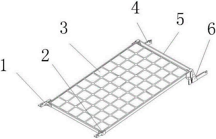
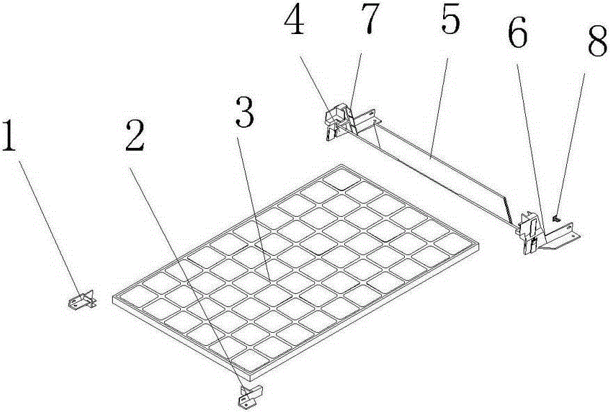
[0029] like figure 1 and 2 As shown, an installation structure of a photovoltaic power generation system includes a left front seat 1 , a right front seat 2 , a left rear seat 4 and a right rear seat 6 installed on four corners of a photovoltaic module 3 . A baffle plate 5 is connected between the left rear seat 4 and the right rear seat 6, and the baffle plate 5 is a profile, which is uniformly integrally formed on the opposite inner surface of the left rear seat 4 and the right rear seat 6 and has the same cross section as the baffle plate profile. The baffle plate connecting protrusion 7, the two ends of the baffle plate 5 are inserted respectively on the baffle plate connecting protrusion 7 of the left rear seat and the right rear seat, thereby realizing the connection of the baffle plate with the left rear seat and the right rear seat.

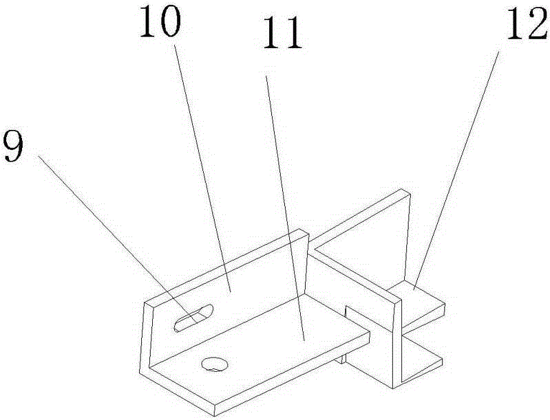
[0030] like image 3 As shown, the left front seat 1 includes a mounting base main body 12 , which is at a right angle, and the mounti...

Embodiment 2

[0037] like Figure 10 As shown, the difference from Embodiment 1 is that frame boards 21 are installed on the four sides of the photovoltaic module 3, and the frame board 21 is connected to the photovoltaic module 3 first, and then the front seat 18 and the rear seat 17 are installed on the frame board superior. The frame plate 21 is a profile structure. On the inner side of the front seat and the rear seat, there are protrusions that match the profile cross-section. Connections to front and rear seats. When carrying out, the auxiliary packing bracket 19 is fixed on the frame plate 21, which is convenient for transportation.

Embodiment 3

[0039] like Figure 11 and 12 As shown, the difference from Embodiment 1 is that the main body 12 of the mounting seat of the left front seat is matched with the right angle of the photovoltaic module, and a groove 14 is opened on the positioning plate 10 on the side of the main body 12 of the mounting seat. Similarly, in the left rear seat The positioning plate 10 on one side of the main body 12 of the mounting seat is provided with a protrusion 15 matching with the groove 14 .

[0040] At the same time, on the positioning plate 10 of the left front seat and the left rear seat, a connecting hole 9 is also provided, and the positioning plates of the left front seat and the left rear seat are connected together, and then passed through the connecting hole 9 through the pin shaft 8 to vertically The two photovoltaic modules arranged are fixed to each other.


PUM


Abstract

The invention relates to a mounting structure and discloses a mounting structure of a photovoltaic power generation system. Mounting bases are respectively arranged at four legs of a photovoltaic module; each mounting base comprises two front seats and two rear seats, which are located at the front end and the rear end of the photovoltaic module; a transverse connection of the photovoltaic module is achieved by two connected mounting bases in the same row through mounting members in the transverse connection; a longitudinal connection of the photovoltaic module is achieved by two connected mounting bases in the same column through the mounting members in the longitudinal connection; and meanwhile, an electric connection member is also arranged between the two connected mounting bases. The mounting structure of the photovoltaic power generation system provided by the invention is simple in structure, convenient to mount, good in connection firmness after components are spliced to one another, and high in reliability, and can achieve transverse and longitudinal two-way connections according to the size of a site; and the technical problems that a connector in the prior art is complicated in structure and low in reliability and only can achieve a one-way connection are solved.

Description

technical field [0001] The invention relates to an installation structure, in particular to an installation structure of a photovoltaic power generation system that can conveniently install photovoltaic modules according to the installation environment. Background technique [0002] As a huge amount of renewable energy, solar energy reaches the surface of the earth every day, which is equivalent to the energy of burning trillions of barrels of oil. The most notable advantage of developing and utilizing abundant solar energy resources is that there is no pollution or only a small amount of pollution to the environment. therefore. Solar energy is not only an energy that needs to be supplemented urgently in the near future, but also the basis of the future energy structure. As an emerging green energy, solar photovoltaic power generation has been widely used. In the existing patent document: "a photovoltaic module installation structure and its installation method (CN2012102...

Claims


Application Information

Patent Timeline
Patent Type & Authority Applications(China)
IPC IPC(8): H02S20/20
CPCH01L31/042H01L31/048H01L31/05H02S20/20Y02E10/50
Inventor 郑杭徐乐吴克明杨明江胡根应
Owner VERSOLSOLAR HANGZHOU
Why Eureka
Try Eureka