
Locking mechanism

A technology for locking mechanism and fastening parts, which is applied in the direction of cabinet/cabinet/drawer parts, etc., which can solve the inconvenient operation of the screw-in locking mechanism, the locking mechanism is easy to get stuck, and cannot be locked normally and other problems, to achieve the effect of excellent locking effect, simple structure and improved service life

Active Publication Date: 2016-01-20
成都瑞雪丰泰精密电子股份有限公司
View PDF3 Cites 12 Cited by
  • Summary
  • Abstract
  • Description
  • Claims
  • Application Information

AI Technical Summary

Problems solved by technology

[0004] After years of production practice and continuous optimization and improvement of the processing technology, our company found the following problems in the production, test and use of the above locking mechanism: the thread on the aluminum alloy parts is easy to rot; the five-joint locking The mechanism is easy to get stuck; the screw-in locking mechanism is inconvenient to operate when it is pre-tightened (because when the fixed block is fixed on the module or board, the upper sliders, screw blocks and top blocks at both ends are not in the pre-tightened state. These parts will rotate freely along the screw axis, and will be stuck during pre-tightening, and cannot be locked normally)

Method used


Image

  • Locking mechanism
  • Locking mechanism

Examples


Embodiment 1

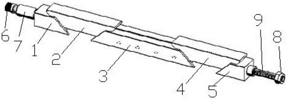
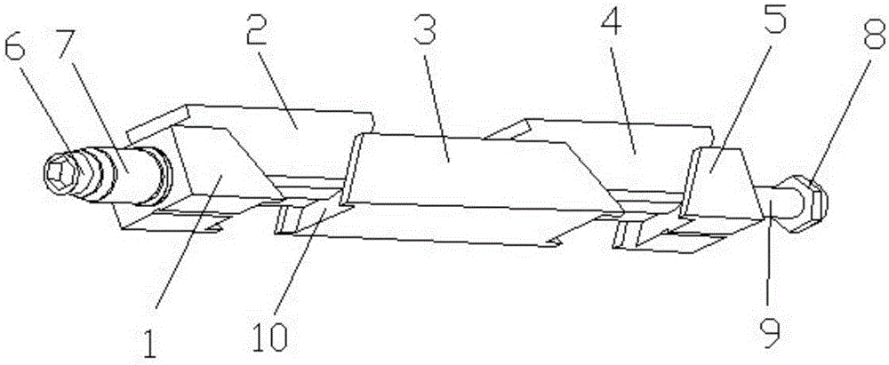
[0026] Such as figure 1 , 2 As shown, the present invention provides a locking mechanism, including a screw rod 9, and fastening components that are sequentially threaded on the screw rod 9 and cooperate with each other, a top block 1, a first upper slider 2, a lower slider 3, The second upper slider 4, screw block 5, nut 8; both ends of the first upper slider 2 and the second upper slider 4 are wedge-shaped surfaces with an angle of α, and the top block 1 and the second upper slider The adjacent end of an upper slider 2, the two ends of the lower slider 3, and the adjacent end of the screw block 5 and the second upper slider 4 are wedge-shaped grooves 10 with an angle of α. , the wedge-shaped groove 10 is matched with the wedge-shaped surface; α=46°;

[0027] The fastening part includes a step 6 integrally connected to the left end of the screw rod 9, a spring threaded on the screw rod 9, and a sleeve structure 7 threaded on the screw rod 9 and used to cover the spring , t...

Embodiment 2

[0030] The nut 8 is a stainless steel rivet nut.

[0031] Other structures in this embodiment are the same as those in Embodiment 1.

Embodiment 3

[0033] The screw 9 is a stainless steel screw.

[0034] Other structures in this embodiment are the same as those in Embodiment 2.


PUM


Abstract

The present invention provides a locking mechanism, comprising a screw, and a fastening component, a top block, a first upper sliding block, a lower sliding block, a second upper sliding block, a screw block and a nut which are successively arranged on the screw in a penetrated way and cooperate with each other; wherein two ends of first upper sliding block and the second upper sliding block are both wedge-shaped surfaces with the angle of alpha, the end portion of the top block adjacent to the first upper sliding block, two ends of the lower sliding block, and the end portion of the screw block adjacent to the second upper sliding block are all wedge grooves having the angle of alpha, the wedge grooves are matched with the wedge-shaped surfaces; and the alpha is an acute angle. The locking mechanism of the present invention has the beneficial effects of simple structure, smooth cooperation of all portions, convenient use, assembling and disassembling, capacity of preventing overturn of a wedge block, having a self-aligning function, and excellent locking effect.

Description

technical field [0001] The invention belongs to the field of modularized cabinets, and in particular relates to a locking mechanism. Background technique [0002] The principle of the locking mechanism is to use the wedge-shaped device to make the displacement between the slider, the screw block and the fixed block along the direction of the inclined plane under the rotation of the screw, so that the printed board, the heat conduction strip and the chassis wall are effectively restricted. It is convenient for disassembly, and it is an essential part for the modular design system. The main function is to prevent the PCB board (printed board) and the module from being damaged in the environment of high impact and vibration, so as to improve the reliability and provide a heat dissipation channel from the board, the module to the chassis. It is mainly used for liquid-cooled chassis, ATR chassis, VPX reinforced shielding system chassis, CPCI shielded chassis and other modules an...

Claims


Application Information

Patent Timeline
Patent Type & Authority Applications(China)
IPC IPC(8): H05K5/02
Inventor 赵明
Owner 成都瑞雪丰泰精密电子股份有限公司
Learn More