
A seeder scriber
A liner and seeder technology, applied in planting methods, applications, agriculture, etc., can solve the problems of inconvenient maintenance, inconvenient operation, inflexible lifting, etc., achieve convenient disassembly and maintenance, convenient operation, and speed up the conversion time Effect
- Summary
- Abstract
- Description
- Claims
- Application Information
AI Technical Summary
Problems solved by technology
Method used
Image

Examples
Embodiment Construction
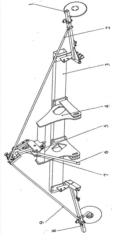
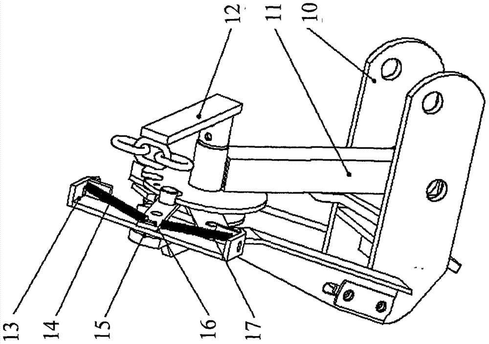
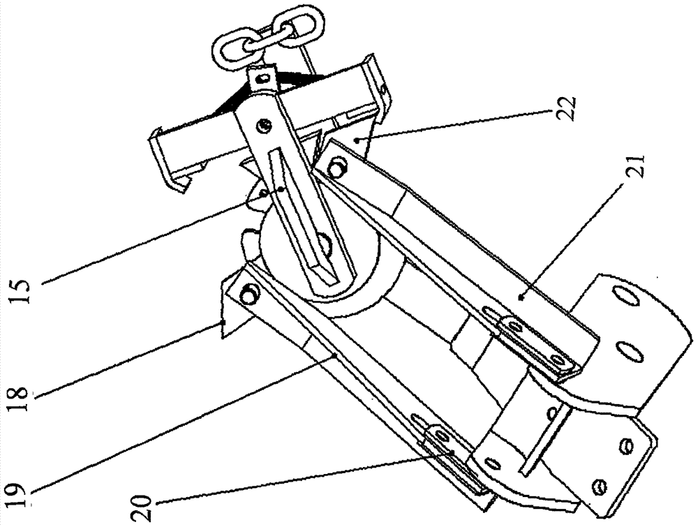
[0011] When the seeder operates on the cultivated land, the center pull rod 6 is controlled to descend so that the seeder is in working condition. like figure 1 As shown, the right marker arm assembly 8 is in contact with the cultivated land, and the left marker arm assembly 1 is off the ground. Now the right limit connecting frame welding 22 and the rotating frame welding 15 fit together and are fixed together by the spring fixing frame welding 13. When the scriber needs to be converted, the central pull rod 6 rises to drive the base welding 10 to rotate and rise. Along with base welding 10 rotation rises, drive left lifting movable plate 19, right lifting movable plate 21 to move upwards, when it moves to the highest point, right limit connecting frame welding 22 separates with spring fixed frame welding 13, spring The fixed frame welding 13 rotates to the left under the elastic force of the left spring 14 and is in a suspended state. At this time, the left scriber support...
PUM
 Abstract
Description
Claims
Application Information