Crusher with good crushing effect

The technology of a pulverizer and a pulverization chamber, which is applied in the direction of grain processing, etc., can solve problems such as the unsatisfactory pulverization effect, the inconvenient handling of the pulverizer, and the inability to achieve the pulverization effect, etc., so as to achieve easy promotion, avoid power waste, and structural simple effect

Inactive Publication Date: 2016-01-27
嘉善远大新型墙体有限公司
View PDF7 Cites 7 Cited by
  • Summary
  • Abstract
  • Description
  • Claims
  • Application Information

AI Technical Summary

Problems solved by technology

[0002] Many building materials are used in construction projects. Today's building bricks mostly use insulation bricks, because insulation bricks are different from traditional bricks, and the materials need to be specially prepared. During the production process of insulation bricks, the raw materials need to be crushed, Stirring, and waste insulation bricks and unqualified products also need to be crushed for recycling. The crusher is a machine that crushes large-sized solid raw materials to the required size. Many places need to use the crusher. In many ways, there are many Resources can be reused after crushing, but these resources are often neglected and wasted by people. The structure of traditional crushers is too simple, and the effect of crushing is not very ideal, which cannot meet people's requirements. Moreover, traditional crushers are more expensive. Yes, a lot of energy will be wasted during crushing, and it cannot achieve a good crushing effect, and after the traditional pulverizer is crushed, a lot of materials will remain in the pulverizer, causing waste
Moreover, the traditional pulverizer is not very convenient to carry

Method used


Image

  • Crusher with good crushing effect
  • Crusher with good crushing effect
  • Crusher with good crushing effect

Examples


Embodiment Construction

[0015] The technical solution of this patent will be further described in detail below in conjunction with specific embodiments.

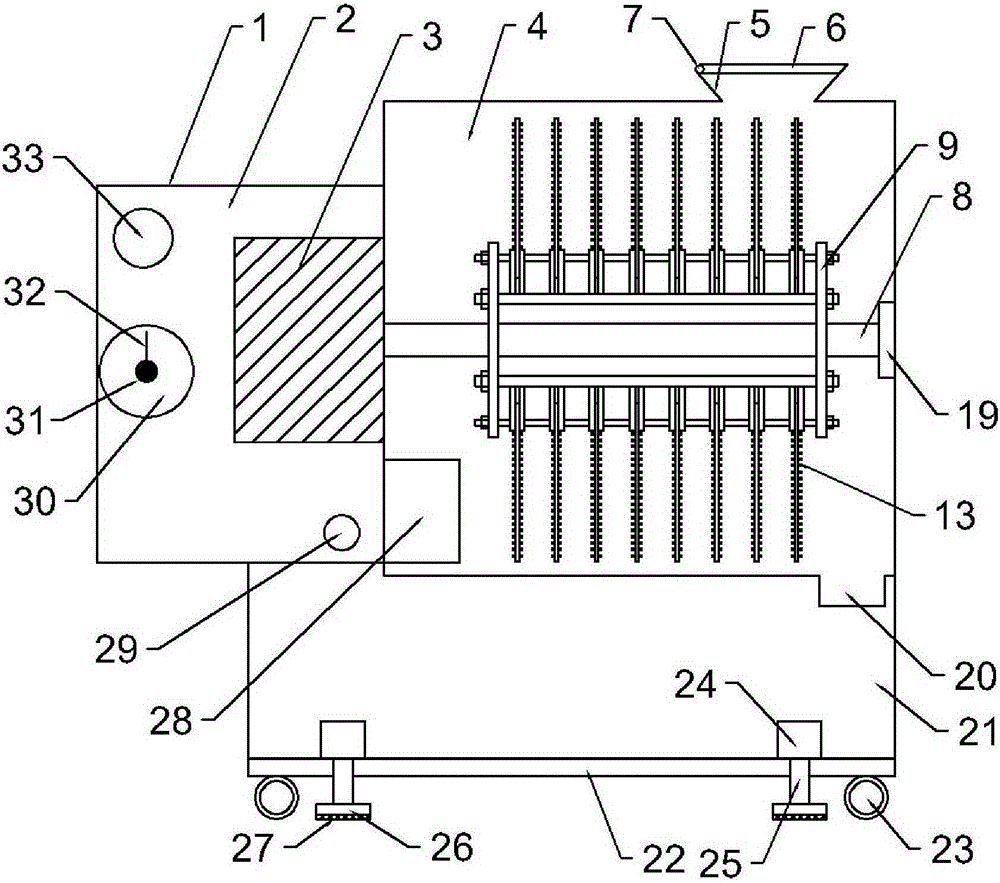
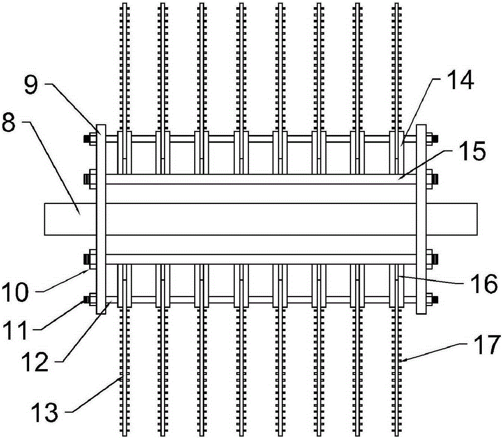
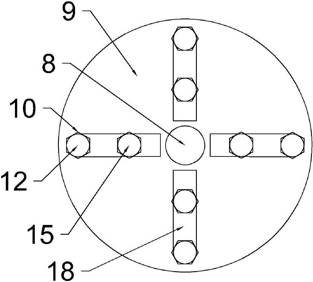
[0016] see Figure 1-4 , a pulverizer with good crushing effect, comprising a body 1, the body 1 includes a motor chamber 2 on the left side, a pulverization chamber 4 on the right side, and a support frame 21 arranged at the bottom of the motor chamber 2 and the pulverization chamber 4, the The motor chamber 2 is fixedly connected with the crushing chamber 4, the motor chamber 2 is provided with a motor 3, the top of the crushing chamber 4 is provided with a feeding funnel 5, and the left side of the feeding funnel 5 is connected with a cover plate 6 through a rotating shaft 7, and the crushing chamber 4 There is a crushing cutter inside, and the crushing cutter includes a rotating shaft 8 and a spoke 9, the left end of the rotating shaft 8 is connected with the motor 3, the right end of the rotating shaft 8 is connected with a bearing 19, and the...


PUM


Abstract

The invention discloses a crusher with good crushing effect. The crusher comprises a machine body, wherein the machine body comprises a motor room, a crushing room and a supporting frame which is arranged on the bottoms of the motor room and the crushing room; a motor is arranged in the motor room; the top end of the crushing room is provided with a feeding funnel; a crushing tool is arranged in the crushing room; the crushing tool comprises a rotary shaft and wheel spokes; through holes are formed in the wheel spokes; the wheel spokes are fixedly connected through a blade string rod; the wheel spokes are fixedly connected through a supporting beam; the blade string rod is in nested connection with blades; the blades are provided with convex points which are uniformly distributed; the right side of the bottom of the crushing room is further provided with a discharge hole; the bottom of the supporting frame is provided with a bottom plate; an inverted hydraulic lifting jack is arranged on the bottom plate; the output shaft of the hydraulic lifting jack is connected with a base; the bottom of the base is further provided with an anti-skidding pad; and the bottom of the bottom plate is further provided with roller wheels. The crusher is simple in structure, relatively complete in processing, convenient for replacing a damaged blade, environmentally-friendly, economical, convenient for moving a machine body, very convenient, and easy to popularize.

Description

technical field [0001] The invention relates to a pulverizing device, in particular to a pulverizer with good pulverizing effect. Background technique [0002] Many building materials are used in construction projects. Today's building bricks mostly use insulation bricks, because insulation bricks are different from traditional bricks, and the materials need to be specially prepared. During the production process of insulation bricks, the raw materials need to be crushed, Stirring, and waste insulation bricks and unqualified products also need to be crushed for recycling. The crusher is a machine that crushes large-sized solid raw materials to the required size. Many places need to use the crusher. In many ways, there are many Resources can be reused after crushing, but these resources are often neglected and wasted by people. The structure of traditional crushers is too simple, and the effect of crushing is not very ideal, which cannot meet people's requirements. Moreover, ...

Claims


Application Information

Patent Timeline
Patent Type & Authority Applications(China)
IPC IPC(8): B02C18/14B02C18/18B02C23/18
Inventor 王建国
Owner 嘉善远大新型墙体有限公司
Why Eureka
Try Eureka