Deburring and rounding device

A rounding and deburring technology, which is applied in the direction of gear teeth, manufacturing tools, mechanical equipment, etc., can solve the problems of excessive distance, high investment cost, and inability to realize tangential transition, etc., and achieve automatic contact and simple device technology Effect

Inactive Publication Date: 2018-09-21
ZF FRIEDRICHSHAFEN AG
View PDF5 Cites 1 Cited by
  • Summary
  • Abstract
  • Description
  • Claims
  • Application Information

AI Technical Summary

Problems solved by technology

If an industrial robot (according to DE 10 2009 020 771 A1) is also used, there is the problem that the limited precision of said industrial robot can lead to too deep a dive of the quarter-round milling cutter or to a Excessive distance between filleted workpiece edges
As a result, the desired tangential transition of the fillet to the adjacent workpiece surface (along the entire workpiece edge) cannot be achieved, especially when the workpiece has complex shapes, such as for gears
[0007] In contrast to this, CNC machines can be used for the precise guidance of the quarter-round milling cutter along the edge of the workpiece to be rounded, the investment costs of which are prohibitively high

Method used


Image

  • Deburring and rounding device

Examples


Embodiment Construction

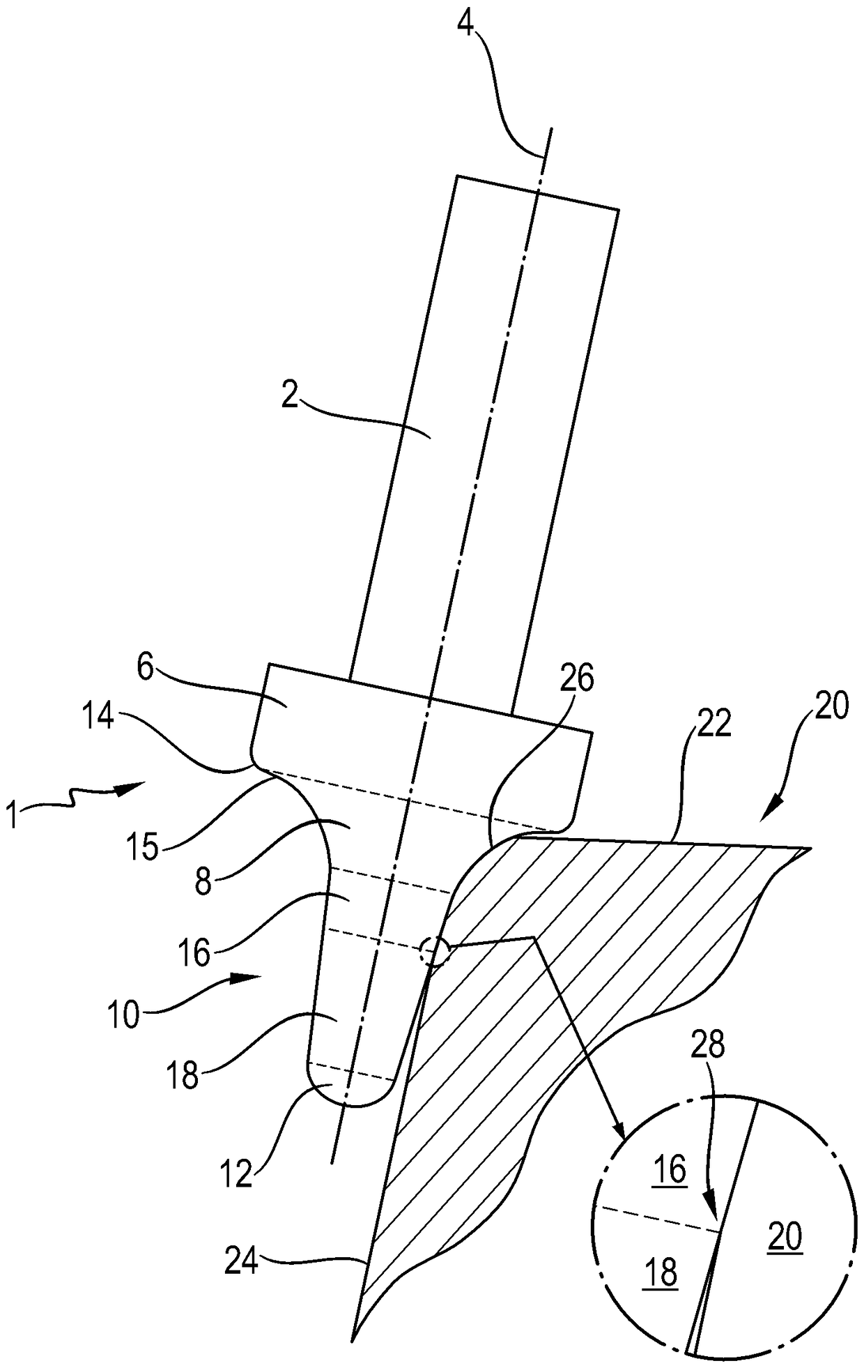
[0029] The milling head 1 is fastened to a rod 2 , which is driven in rotation about an axis of rotation 4 by an industrial robot, not specifically shown, and can be positioned and pivoted largely freely in space here.

[0030] Starting from the shank 2, the milling head 1 has the following rotationally symmetrical sections, which jointly and integrally form the milling head 1: a base section 6, an outer section adjoining the base section 8. A cone section 10 adjacent to said outer section and finally a head section 12 adjacent to said cone section. The base section 6 forms the region of the milling head 1 with the largest diameter and is substantially cylindrical. In the region of the transition to the outer section 8 , the base section 6 has a convex rounded corner 14 . Viewed in longitudinal section of the milling head 1 , the outer section 8 is concavely curved, so that its diameter decreases significantly from the radius 14 through its outermost edge region 15 in the dir...


PUM


Abstract

The present invention relates to a deburring and rounding device, and particularly a deburring and rounding device for the edge of a complex formed workpiece. For a gear, the edge of the complex formed workpiece occurs, for example, between the end face and the tooth flank. The device includes an industrial robot. The industrial robot guides a rotary milling head along the edge of the complex formed workpiece. The milling head is designed thus, and therefore the extremely weak edge persists even if the guiding is performed accurately.

Description

technical field [0001] The invention relates to a deburring and rounding device for workpiece edges. Background technique [0002] In the case of gears, on each end face of the gear, which is arranged perpendicular to the axis of rotation, there is a complexly shaped workpiece edge, which is arranged on the one hand on the end face and on the other hand on the flank or root of the individual teeth Or between the tops. [0003] In the case of the manufacture of gears or other workpieces of this type, burrs usually remain on the edges of these workpieces, which should be removed. In addition, tooth flanks are usually provided on the workpiece edge, so that the tooth flanks cannot be damaged during assembly of this type of gear, especially if the gear is tilted. It is known from the prior art to manually deburr and chamfer workpiece edges. Manually chamfering complexly shaped workpiece edges, such as gear wheels, is time-consuming and complicated and requires a lot of practi...

Claims


Application Information

Patent Timeline
Patent Type & Authority Patents(China)
IPC IPC(8): B23C3/12B23F19/10B23C5/02
CPCB23C3/12B23C5/14B23C2210/126B23C2210/326B23F19/10
Inventor A.鲁迪M.施平齐克
Owner ZF FRIEDRICHSHAFEN AG
Why Eureka
Try Eureka