Slide valve grinding clamp used for disc grinder and clamping method for slide valves

A disc grinding and grinding fixture technology, applied in the direction of the working carrier, can solve the problems of increasing the loss of the grinding disc, affecting the grinding quality, and low grinding efficiency, and achieve the effects of eliminating movement, stabilizing the grinding quality, and improving the grinding efficiency

Active Publication Date: 2016-01-27
MEISHAN CRRC BRAKE SCI & TECH CO LTD
View PDF7 Cites 2 Cited by
  • Summary
  • Abstract
  • Description
  • Claims
  • Application Information

AI Technical Summary

Problems solved by technology

[0004] like figure 2 As shown, the main problems of the existing slide valve grinding fixture are: 1. The clamp 11 and the slide valve 2 are in contact with the grinding disc 4 at the same time, and the grinding disc also grinds the fixture while grinding the slide valve, which increases the loss; 2. There is no clamping between the slide valve 2 and the fixture 11, which is a clearance fit. During the rotation of the fixture, the slide valve will move in the fixture, which is prone to corner drop and affects the grinding quality; 3. The slide valve There is no counterweight, and the pressure required for grinding is only the slide valve’s own weight. Since the slide valve is light, only 0.25kg, the pressure on the grinding disc is small, resulting in low grinding efficiency

Method used


Image

  • Slide valve grinding clamp used for disc grinder and clamping method for slide valves
  • Slide valve grinding clamp used for disc grinder and clamping method for slide valves
  • Slide valve grinding clamp used for disc grinder and clamping method for slide valves

Examples


Embodiment Construction

[0029] Below in conjunction with accompanying drawing, the present invention is described in detail.

[0030] In order to make the object, technical solution and advantages of the present invention clearer, the present invention will be further described in detail below in conjunction with the accompanying drawings and embodiments. It should be understood that the specific embodiments described here are only used to explain the present invention, not to limit the present invention.

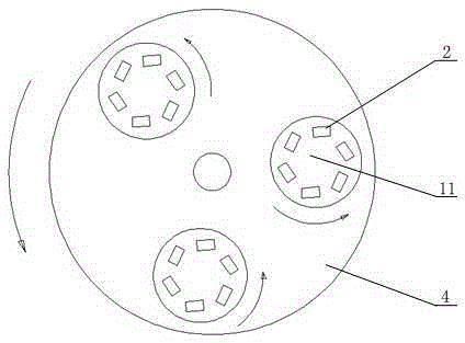
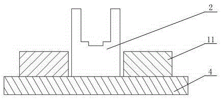
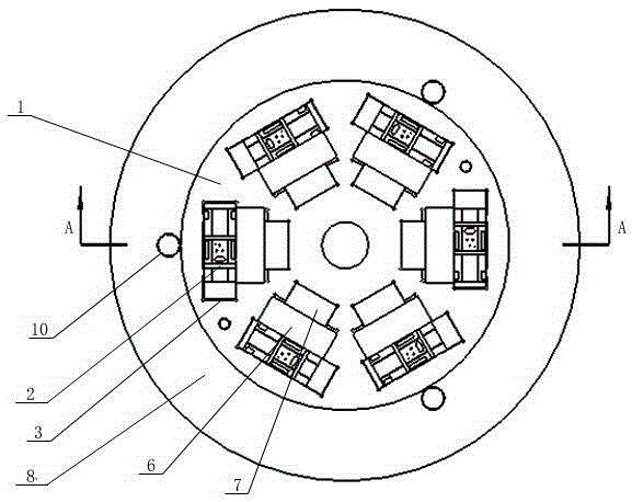
[0031] Such as image 3 , 4 As shown in and 5, a slide valve grinding fixture for a disc grinder includes a slide valve clamping disc 1, on which a plurality of slide valve clamping discs 1 are provided for clamping the slide valve 2 clamping cavity 3, the slide valve 2 is placed in the corresponding clamping cavity 3 and the slide valve 2 and the slide valve clamping disc 1 are pressed and fixed together by the pressing mechanism, and the multiple slide valves 2 are The shaft center of the sli...


PUM


Abstract

The invention discloses a slide valve grinding clamp used for a disc grinder and a clamping method for slide valves. The slide valve grinding clamp comprises a slide valve clamping disc. A plurality of clamping cavities used for clamping the slide valves are arranged on the slide valve clamping disc. The slide valves are arranged in the corresponding clamping cavities and pressed tightly on and fixed to the slide valve clamping disc through a pressing mechanism. The multiple slide valves form an integral structure after being clamped on the slide valve clamping disc. The surfaces to be ground of the multiple slide valves are located on the same horizontal plane. The slide valve grinding clamp clamping the multiple slide valves is arranged on a grinding disc of the disc grinder, the surfaces to be ground of the slide valves are in contact with the grinding disc, and a gap exists between the slide valve clamping disc and the grinding disc. After the slide valves are clamped through the slide valve grinding clamp, the clamp can be effectively prevented from being in contact with the grinding disc, displacement of the slide valves in the self-rotation process of the clamp is eliminated, and meanwhile the grinding efficiency can be improved.

Description

technical field [0001] The invention belongs to the technical field of grinding equipment, and in particular relates to a sliding valve grinding fixture for a disk grinding machine and a clamping method for the sliding valve. Background technique [0002] The slide valve is a core component of the 120-type freight car air control valve for the main brake machine of railway freight cars at present, and it mainly plays the role of sealing and connecting the air circuit. During the processing, the working surface of the slide valve needs to be ground with a disc grinder. [0003] Such as figure 1 As shown, the process of grinding the slide valve in the existing disc grinder is as follows: the grinder is started, the grinding disc rotates to drive the fixture and the slide valve in the fixture to rotate around its own center of circle, and the slide valve and the grinding disc form a relative rotation, and the grinding The abrasive in the disc begins to micro-cut the working s...

Claims


Application Information

Patent Timeline
Patent Type & Authority Applications(China)
IPC IPC(8): B24B37/27
CPCB24B37/27
Inventor 周超洪宋强杨金龙王开恩
Owner MEISHAN CRRC BRAKE SCI & TECH CO LTD
Why Eureka
Try Eureka