Mechanical type intermediate case vacuum-pumping and pressurization apparatus and application method thereof
A pressurizing device and intermediate box technology, applied in the direction of transportation and packaging, railway car body parts, sanitary equipment, etc., can solve the problems of unfavorable energy saving, consumption of compressed air, waste of compressed air, etc., and achieve energy saving, low cost and good structure simple effect
- Summary
- Abstract
- Description
- Claims
- Application Information
AI Technical Summary
Problems solved by technology
Method used
Image
Examples
Embodiment 1
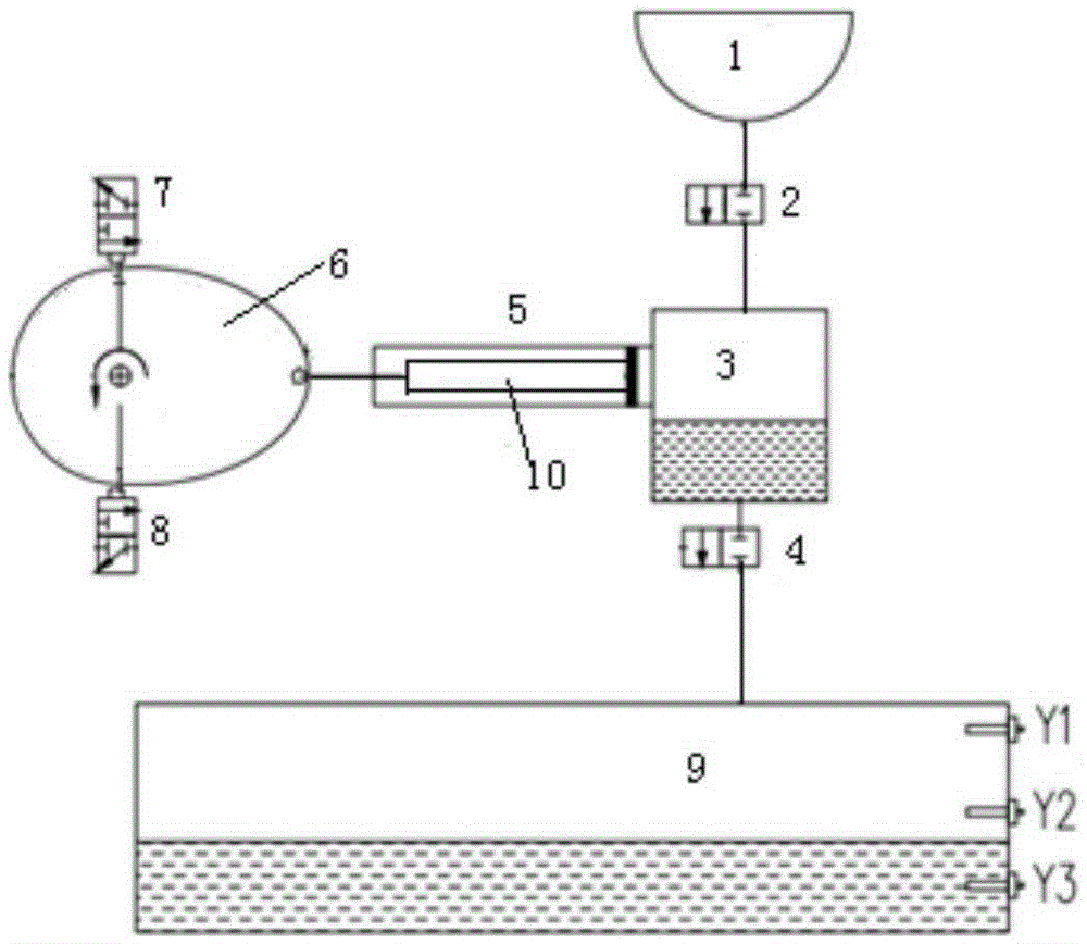
[0034] The mechanical intermediate box vacuuming and pressurizing device includes: rollers, one side of the rollers is provided with the first manual valve 7 for opening the dirt generator 1 (toilet), and the other side is provided with the first manual valve 7 for opening the intermediate box 3. 2. Manual valve 8, the roller rotates around the axis, and a protrusion is provided in the circumferential direction of the roller; the middle box 3, the top of the middle box 3 is connected with the dirt generator 1, and the bottom of the middle box 3 is connected with the dirt box 9 ; Cylinder 5, the piston rod 10 in the cylinder 5 is connected to the roller through the tensioning mechanism, and the inner cavity of the cylinder 5 is communicated with the middle box 3; a liquid level gauge is arranged in the dirt tank 9, which is used to send a signal to the controller. When case 9 inner volume is not enough, can notify the staff in time to clean up by alarm device.
[0035] The prot...
Embodiment 2
[0049] Mechanical intermediate box vacuuming and pressurizing device, including: a roller, one side of the roller is provided with a first manual valve 7 for opening the dirt generator 1, and the other side is provided with a second manual valve for opening the intermediate box 3 Valve 8, the roller rotates around the shaft, and a protrusion is provided in the circumferential direction of the roller; the roller is a cam 6, and the first manual valve 7 is arranged on one side of the short axis of the cam 6, and the second hand The movable valve 8 is located on the other side of the short axis of the cam 6, the piston rod 10 is connected to the long axis of the cam 6 by the tension mechanism, and the protrusion is located at one end of the long axis of the cam 6; the middle box 3, the middle box The top of 3 is connected with the dirt generator 1, and the bottom of the middle box 3 is connected with the dirt box 9; the cylinder 5, the piston rod 10 in the cylinder 5 is connected ...
PUM
 Abstract
Description
Claims
Application Information
 - R&D
- Intellectual Property
- Life Sciences
- Materials
- Tech Scout
- Unparalleled Data Quality
- Higher Quality Content
- 60% Fewer Hallucinations
Browse by: Latest US Patents, China's latest patents, Technical Efficacy Thesaurus, Application Domain, Technology Topic, Popular Technical Reports.
© 2025 PatSnap. All rights reserved.Legal|Privacy policy|Modern Slavery Act Transparency Statement|Sitemap|About US| Contact US: help@patsnap.com

