
Exhausts for scooter vehicles

An exhaust device and pedal-type technology, which is applied to exhaust devices, mufflers, motorcycles, etc., can solve problems such as the shape of the concave portion is easily restricted, the distance between the rear wheel and the exhaust muffler is large, and it is difficult to form a sufficiently large concave portion. , to achieve good appearance, ensure freedom, and maintain the effect of appearance

Active Publication Date: 2017-12-15
HONDA MOTOR CO LTD
View PDF5 Cites 0 Cited by
  • Summary
  • Abstract
  • Description
  • Claims
  • Application Information

AI Technical Summary

Problems solved by technology

[0007] However, in recent years, in order to realize the detoxification of harmful substances contained in exhaust gas, catalytic converters (hereinafter referred to simply as "catalytic converters") are generally installed on the exhaust system. space, a known device that arranges the catalytic converter in the exhaust muffler, however, since the catalytic converter is a relatively large component, it tends to occupy a large space in the exhaust muffler
[0008] Therefore, if a concave portion for moving the rear wheel is formed on the exhaust muffler as shown in Patent Document 1, there is a problem that the shape of the concave portion is easily restricted because the catalytic converter occupies a large space in the exhaust muffler, and it is difficult to form it. A recess large enough and deep enough for the rear wheels to move
[0009] Therefore, in order to secure the necessary space between the rear wheels and the exhaust muffler without removing the exhaust muffler, it is conceivable to move the exhaust muffler to the outside in the vehicle width direction so as to be installed away from the rear wheel, but it is possible There are problems that, when the vehicle is viewed from the rear, the appearance is deteriorated due to the large space between the rear wheels and the exhaust muffler, or the vehicle body is damaged due to the exhaust muffler bulging outward in the vehicle width direction. Upsizing, etc.

Method used


Image

  • Exhausts for scooter vehicles
  • Exhausts for scooter vehicles
  • Exhausts for scooter vehicles

Examples


Embodiment Construction

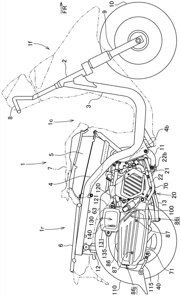
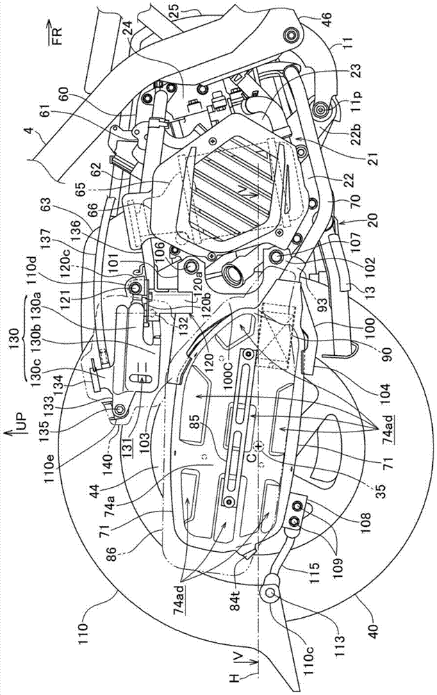
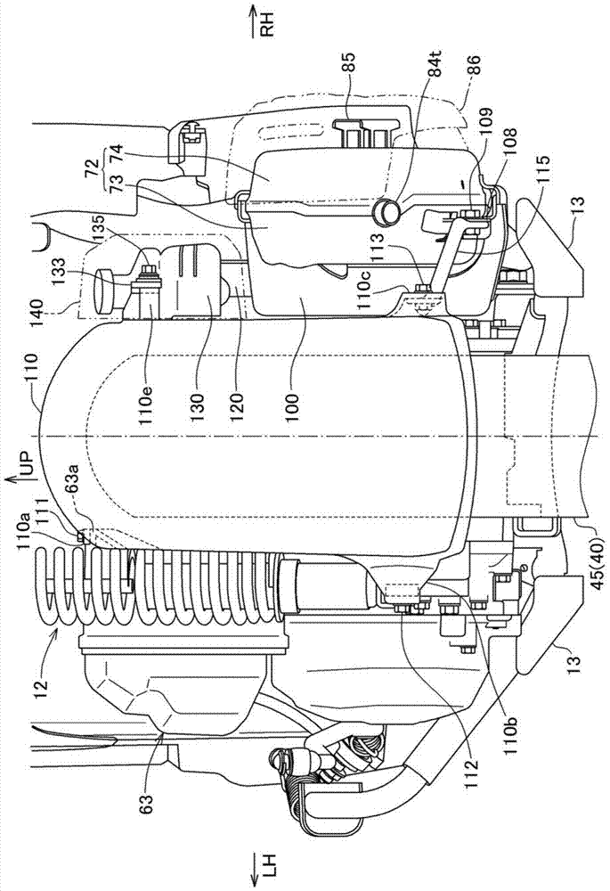
[0052] Refer to the attached Figure 1-12 One embodiment of the present invention will be described.

[0053] figure 1 It is a side view of the scooter-type motorcycle 1 to which one embodiment of the present invention is applied.

[0054] In addition, in the description and claims of this specification, the directions of front, rear, left, and right are generally based on the forward direction of the scooter-type motorcycle 1 according to the present embodiment.

[0055] In the figure, arrow FR indicates the front of the vehicle, LH indicates the left side of the vehicle, RH indicates the right side of the vehicle, and UP indicates the upper side of the vehicle.

[0056] The vehicle body front part 1f and the vehicle body rear part 1r are connected by a lower floor part 1c, and the body frame constituting the skeleton of the vehicle body is roughly composed of a down pipe 3 and a main pipe 4 .

[0057] That is, the downpipe 3 extends downward from the head pipe 2 of the fr...


PUM


Abstract

Catalytic converter in the exhaust muffler, by being arranged so as to avoid the wheel clearance recess after the required size and depth, without detaching the exhaust muffler while avoiding size increase of the body to maintain good appearance replacement of the rear wheel provide an exhaust apparatus for a scooter type vehicle capable of;. on the opposite side side and a power transmission mechanism disposed on one side of rear wheel (40) (31 and 33), internal exhaust muffler with a catalytic converter (90) (71) is disposed, the portion facing the rear wheel axle (35) in rear wheels (40) side of the inner wall of the exhaust muffler (71) (73a), exhaust instrumentation of the scooter-type vehicle rear wheel escape recess (73P) is formed; in location, the catalytic converter (90) is placed in front of the wheel escape recess later in the exhaust muffler (71) (73P) exhaust system.

Description

technical field [0001] The invention relates to an exhaust device of a pedal vehicle. Background technique [0002] In the prior art, a scooter type vehicle is known in which a swingable power unit is supported on a vehicle body frame. The rear wheel axle of the rear part supports the rear wheel from one side, and the other side opposite to the power transmission mechanism arranged on one side of the rear wheel is provided with an exhaust muffler. [0003] A rear wheel axle protruding toward the exhaust muffler is provided at the rear of the power transmission mechanism. Since the hub of the rear wheel is fitted to the rear wheel axle, the hub and the rear wheel axle are fixed together by nuts or the like, so that The rear wheel is installed on the rear wheel axle, so when removing the rear wheel from the vehicle body, it is necessary to release the fixing of the rear wheel by nuts, etc., and move the rear wheel to the side of the exhaust muffler in the direction of the axl...

Claims


Application Information

Patent Timeline
Patent Type & Authority Patents(China)
IPC IPC(8): F01N13/18B62M7/06
CPCY02A50/20
Inventor 三浦胜己
Owner HONDA MOTOR CO LTD
Learn More