
Axial-oil-distribution tilt cylinder plunger type hydraulic motor

A hydraulic motor and oil distribution technology, which is applied in the field of shaft-distributed oil swing cylinder plunger hydraulic motors, can solve the problems of high adjustment sensitivity, deformation, and easy wear of copper pads, so as to improve the working environment, increase the service life, and resist The effect of shock reinforcement

Active Publication Date: 2016-01-27
NINGBO HANZHU HYDRAULIC MOTOR CO LTD
View PDF6 Cites 2 Cited by
  • Summary
  • Abstract
  • Description
  • Claims
  • Application Information

AI Technical Summary

Problems solved by technology

High-speed hydraulic motors are basically divided into gear type, screw type and vane type. Their main characteristics are high speed, small moment of inertia and high adjustment sensitivity; the main characteristics of low-speed hydraulic motors are large displacement, large volume and low speed. There is no need for a deceleration device; however, the structures of these two types of motors are relatively complex, and the additional valve block is large in size, which cannot better meet the needs of use; the working pressure of hydraulic motors in the prior art is relatively low, and the oil distribution method is plane oil distribution Mainly, when working in a high-pressure environment, the copper pad is easy to wear and deform; in addition, due to the high friction, the oil heats up seriously, and the oil temperature of the hydraulic system is overheated, which will cause a series of failures of the hydraulic actuators. problem with normal work

Method used


Image

  • Axial-oil-distribution tilt cylinder plunger type hydraulic motor
  • Axial-oil-distribution tilt cylinder plunger type hydraulic motor
  • Axial-oil-distribution tilt cylinder plunger type hydraulic motor

Examples


Embodiment Construction

[0029] Below in conjunction with specific embodiment, further illustrate the present invention. It should be understood that these examples are only used to illustrate the present invention and are not intended to limit the scope of the present invention. In addition, it should be understood that after reading the teachings of the present invention, those skilled in the art can make various changes or modifications to the present invention, and these equivalent forms also fall within the scope defined by the appended claims of the present application.

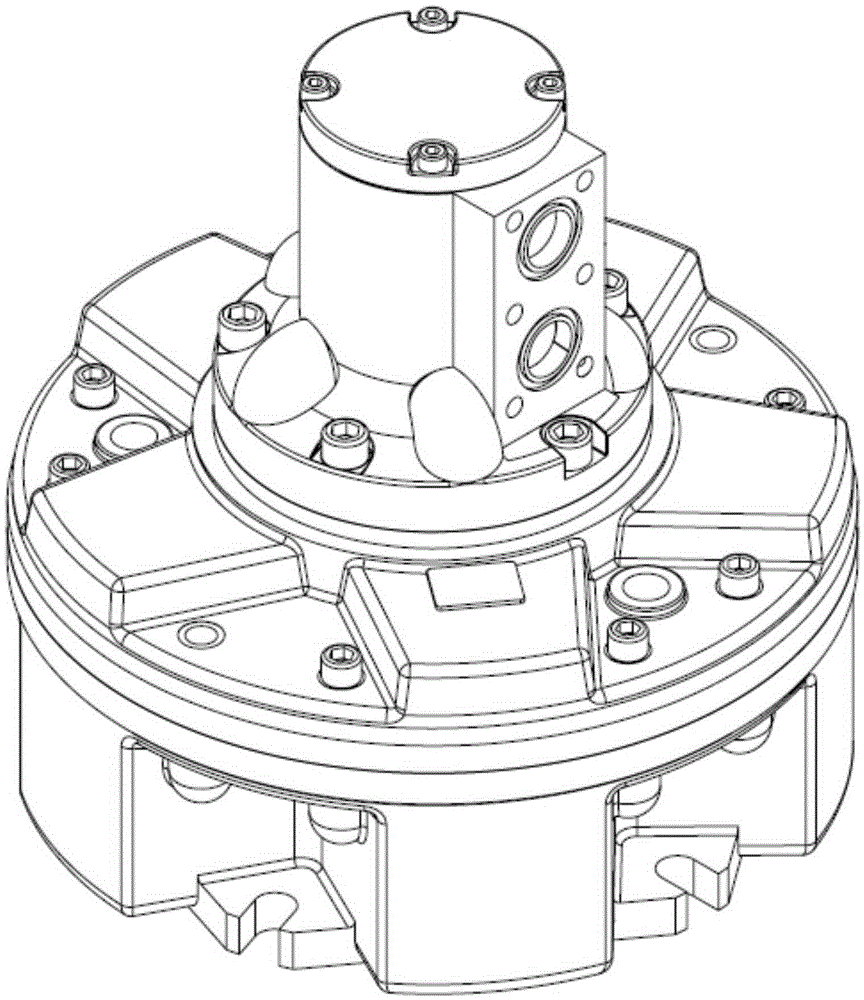
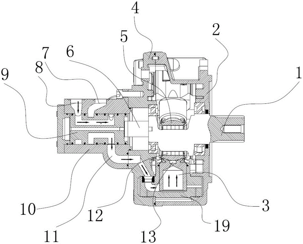
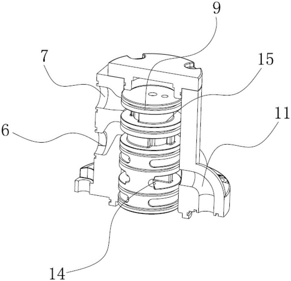
[0030] Such as Figure 1-8 As shown, the embodiment of the present invention relates to a shaft-distributed oil swing cylinder plunger hydraulic motor, which includes a housing and a crankshaft 1, and is characterized in that the crankshaft 1 is installed transversely inside the housing, and the housing An oil pan 10 is installed at one end of the oil pan 10, and an axial oil distributor 9 with one end axially connected to the...


PUM


Abstract

The invention relates to an axial-oil-distribution tilt cylinder plunger type hydraulic motor. The axial-oil-distribution tilt cylinder plunger type hydraulic motor comprises a shell and a crankshaft. The crankshaft is transversely installed inside the shell. An axial oil distributor is installed inside an oil passing disc, wherein one end of the axial oil distributor is axially connected with the crankshaft. The middle of the crankshaft is sleeved with a bearing bush. A tilt cylinder is arranged inside the shell. A plurality of plungers are arranged inside the tilt cylinder around the bearing bush. A first oil inlet and outlet opening and a second oil inlet and outlet opening are formed in the side wall of the oil passing disc side by side. The axial oil distributor is cylindrical. The outer side of the axial oil distributor is axially and sequentially provided with an oil inlet annular groove and an oil outlet annular groove communicated with the first oil inlet and outlet opening and the second oil inlet and outlet opening respectively. A pair of arc grooves is further symmetrically formed in the positions, corresponding to an oil passing channel, of the axial oil distributor. The oil inlet annular groove and the oil outlet annular groove are communicated with the two arc grooves from the interior of the axial oil distributor respectively. The axial-oil-distribution tilt cylinder plunger type hydraulic motor is simple in structure, stable in oil distribution work, not prone to abrasion and capable of solving the problem of oil heating and prolonging the service life.

Description

technical field [0001] The invention relates to the field of hydraulic motors, in particular to a shaft-distributed oil swing cylinder plunger hydraulic motor. Background technique [0002] At present, hydraulic motors have been widely used in various engineering fields. Hydraulic motors generally refer to energy conversion devices that perform output rotary motion and convert hydraulic energy provided by hydraulic pumps into mechanical energy. According to the rated speed of hydraulic motors, they can be divided into High-speed and low-speed two categories. High-speed hydraulic motors are basically divided into gear type, screw type and vane type. Their main characteristics are high speed, small moment of inertia and high adjustment sensitivity; the main characteristics of low-speed hydraulic motors are large displacement, large volume and low speed. There is no need for a deceleration device; however, the structures of these two types of motors are relatively complex, and...

Claims


Application Information

Patent Timeline
IPC IPC(8): F03C1/053F03C1/36
Inventor 吴海荣贺华玲
Owner NINGBO HANZHU HYDRAULIC MOTOR CO LTD
Learn More