
Hydraulic variable pump

A variable pump and hydraulic technology, applied in the field of hydraulic variable pumps, can solve the problems of high energy consumption and low transmission efficiency, and achieve the effect of improving work efficiency

Inactive Publication Date: 2016-01-27
张龙
View PDF7 Cites 0 Cited by
  • Summary
  • Abstract
  • Description
  • Claims
  • Application Information

AI Technical Summary

Problems solved by technology

[0012] In view of the defects of low transmission efficiency and high energy consumption of the existing hydraulic variable pump, the present invention adopts a hydraulic variable pump, which is more energy-saving in transmission and improves work efficiency

Method used


Image

  • Hydraulic variable pump
  • Hydraulic variable pump

Examples


Embodiment Construction

[0028] In order to make the object, technical solution and advantages of the present invention more clear, the present invention will be further described in detail below in conjunction with the examples. It should be understood that what is described here is only a part of the embodiments of the present invention, rather than all the embodiments. Based on the embodiments of the present invention, all other embodiments obtained by persons of ordinary skill in the art without making creative efforts belong to the protection scope of the present invention.

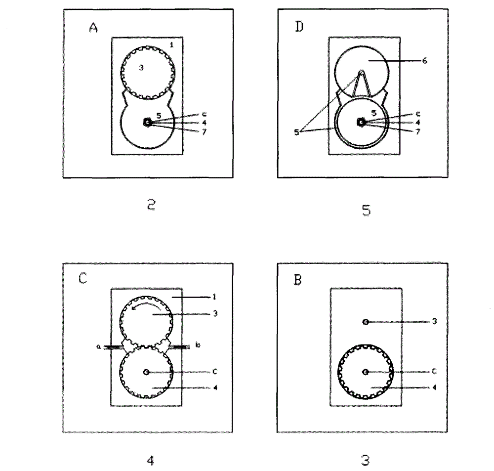
[0029] One of the purposes of the embodiments of the present invention is to provide a hydraulic variable pump, such as figure 1 As shown, it specifically includes the following parts:

[0030] Fixed gear 3, power shaft 16, oil seal 8, fixed card 11, multi-legged fork seal 6, sealing slider 5, with screw 10, sliding gear 4, left end shaft 12, nut 17, sealing cover 15, fancy oil seal 7.

[0031] The fixed gear 3 passes thro...


PUM


Abstract

The invention discloses a hydraulic variable pump. The hydraulic variable pump comprises a fixed gear 3, a power shaft 16, an oil seal 8, a fixing clip 11, a multi-pin fork seal 6, a sealing sliding block 5, a screw 10, a sliding gear 4, a left end shaft 12, a nut 17, a sealing hood 15 and a fancy oil seal 7. When a hydraulic cylinder pushes the sealing sliding block to move rightwards, the forked connection portion of the multi-pin fork seal 6 and the fixed gear 3 is driven to be longer, and the gear portion of the fixed gear 3 is shortened; meanwhile, the right side of the sliding gear 4 enters the sealing hood 15 more, the engaged portion of the fixed gear and the sliding gear is shortened, the displacement is reduced at the same time, and the displacement is improved during reverse motion. The hydraulic variable pump saves more on the aspect of transmission, and improves working efficiency.

Description

【Technical field】 [0001] The invention relates to the field of hydraulic transmission and machinery, in particular to a hydraulic variable pump. 【Background technique】 [0002] Variable displacement pumps are pumps with variable displacement. Variable displacement pumps can be single-acting vane pumps, radial piston pumps or axial piston pumps, and are widely used in hydraulic transmission fields such as metallurgy, mining, engineering machinery, ships, and civil aviation ground equipment. [0003] The variable pump realizes the transformation of the hydraulic system of the injection molding machine from valve control to pump control, and transforms the conventional throttling speed control system into a proportional speed control system, and the control performance index of the whole machine has been improved and improved. Specifically, the proportional variable pump system has the following advantages in addition to the advantages of the conventional proportional control ...

Claims


Application Information

Patent Timeline
Patent Type & Authority Applications(China)
IPC IPC(8): F04B49/00
Inventor 张龙
Owner 张龙
Learn More