Oil return device of compressor, compressor and air conditioner

A compressor and cavity technology, which is applied in the field of compressors, can solve the problems of compressor oil reduction, affecting compressor performance, etc., and achieve the effects of reducing loss, improving performance, and simple structure

Active Publication Date: 2016-01-27
ZHUHAI GREE REFRIGERATION TECH CENT OF ENERGY SAVING & ENVIRONMENTAL PROTECTION
View PDF5 Cites 8 Cited by
  • Summary
  • Abstract
  • Description
  • Claims
  • Application Information

AI Technical Summary

Problems solved by technology

At the same time, since the refrigerant fills the entire exhaust chamber, the lubricating oil in the refrigerant adheres to the upper cover and the partition wall, and eventually a certain amount of refrigerated oil will remain in the exhaust chamber. Over time, the high and low pressure chambers are separated There will be more and more refrigerated oil on the plate, resulting in a decrease in the amount of oil involved in lubrication in the compressor, which will affect the performance of the compressor

Method used


Image

  • Oil return device of compressor, compressor and air conditioner
  • Oil return device of compressor, compressor and air conditioner
  • Oil return device of compressor, compressor and air conditioner

Examples


Embodiment 1

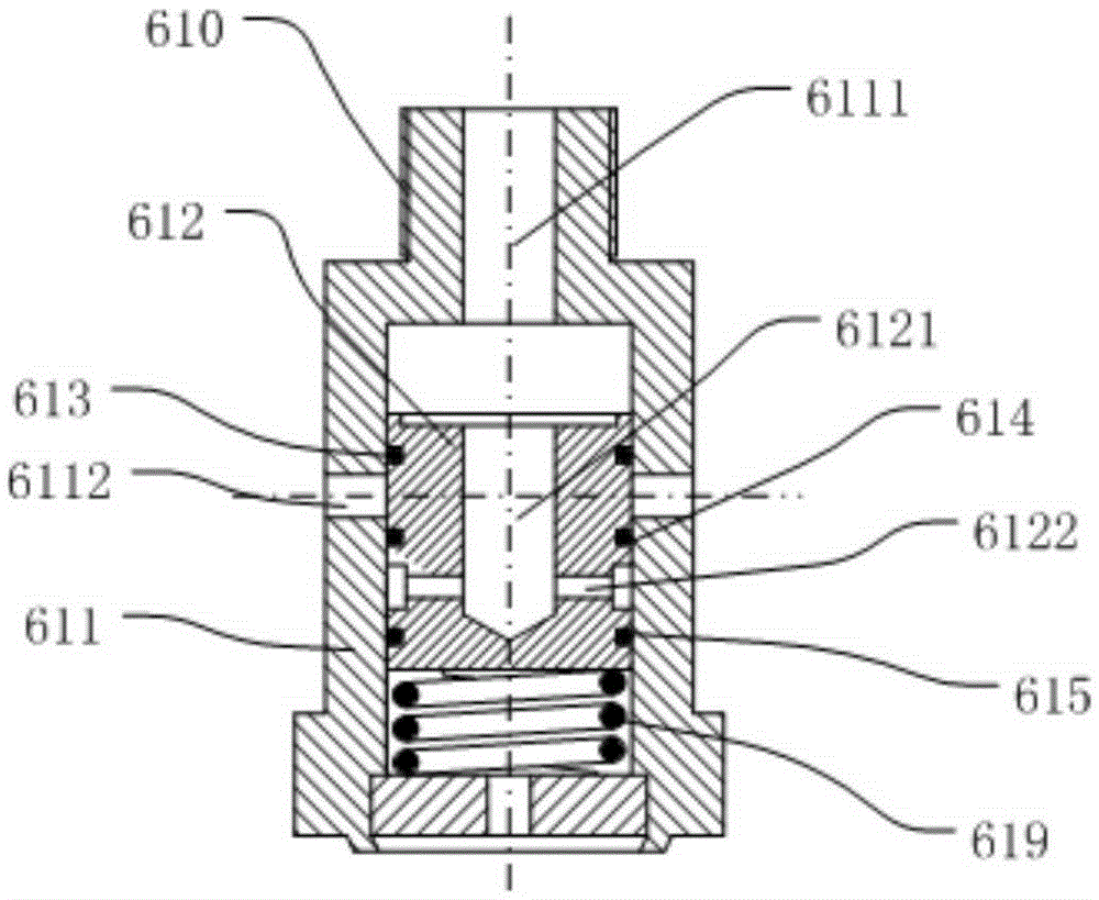
[0030] like Figure 2-3 As shown, the oil return valve 61 in this embodiment includes a valve housing 611 and a valve core 612. A cavity with an upper end opening 6111 is formed in the valve housing 611, and the valve core 612 is arranged in the cavity. And can slide up and down along the inner wall of the cavity in the cavity, so that the valve core 612 has a first position and a second position in the cavity, wherein, in the first position, the oil return valve 61 is in an open state, and in the second position, the oil return valve 61 is in a closed state. Preferably, an elastic member 619 is provided on the lower side of the valve core 612, and the elastic member 619 is preferably a coil spring. In the absence of external force, the valve core 612 acts on the elastic force of the elastic member 619 Down, it can slide from the second position to the first position.

[0031] Specifically, a valve casing oil leakage hole 6112 is opened on the side wall of the valve casing 6...

Embodiment 2

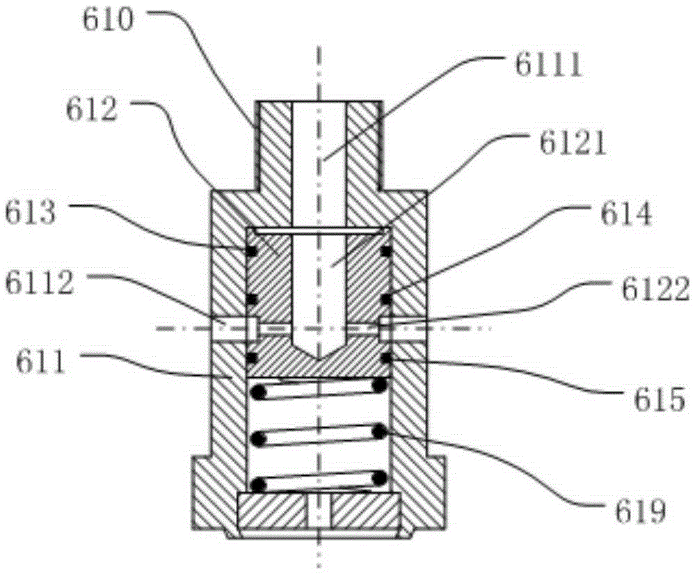
[0034] like Figure 4-5 As shown, the oil return valve 61 in this embodiment is the same as the first embodiment, and also includes a valve casing 611 and a valve core 612, and a cavity with an upper end opening 6111 is formed in the valve casing 611, and the valve core 612 is arranged in the cavity, and can slide up and down along the inner wall of the cavity in the cavity, so that the valve core 612 has a first position and a second position in the cavity, wherein, in the first In the first position, the oil return valve 61 is in an open state, and in the second position, the oil return valve 61 is in a closed state. Preferably, an elastic member 619 is provided on the lower side of the valve core 612, and the elastic member 619 is preferably a coil spring. In the absence of external force, the valve core 612 acts on the elastic force of the elastic member 619 Down, it can slide from the second position to the first position.

[0035] The difference between this embodiment...


PUM


Abstract

The invention relates to an oil return device of a compressor, a compressor and an air conditioner, wherein one end of the oil return device is communicated with an exhaust cavity of the compressor. The oil return device comprises a valve shell and a valve core, wherein a cavity with an open upper end is formed in the valve shell, the valve core is arranged in the cavity and capable of sliding in the cavity up and down along the inner wall of the cavity, so that the valve core has a first position and a second position in the cavity; and at the first position, the oil return device is in an open state, and at the second position, the oil return device is in a closed state. In the oil return device of the compressor, the compressor and the air conditioner, which are disclosed by the invention, by arranging the oil return device on a partition plate for a high-pressure cavity and a low-pressure cavity, residual lubricant oil in the exhaust cavity can be timely recovered, thus the loss of the lubricant oil is reduced.

Description

technical field [0001] The invention relates to the technical field of compressors, in particular to a compressor oil return device and a compressor and an air conditioner provided with the oil return device. Background technique [0002] The scroll compressor has the characteristics of simple structure, small size, light weight, low noise, high mechanical efficiency and stable operation. The oil circuit system in the compressor plays an important role in its performance. However, the high-pressure exhaust chamber formed by the upper cover assembly of the ordinary low-pressure chamber scroll compressor and the high-low pressure chamber partition plate is usually not equipped with an oil return device, resulting in Lubricating oil remaining in the exhaust chamber cannot be recycled. [0003] In an ordinary scroll compressor, after the refrigerant containing a certain amount of oil is compressed by the dynamic and static disks, it enters the high pressure formed by the upper ...

Claims


Application Information

Patent Timeline
Patent Type & Authority Applications(China)
IPC IPC(8): F04C29/02F04C18/02
Inventor 李海港郭求和曹贞文胡余生李小雷
Owner ZHUHAI GREE REFRIGERATION TECH CENT OF ENERGY SAVING & ENVIRONMENTAL PROTECTION
Why Eureka
Try Eureka