Locknut for rotor of gas turbine and machining methods of locknut

A technology of anti-loosening nuts and gas turbines, applied in the direction of nuts, screws, bolts, etc., can solve problems such as limited installation space, and achieve the effects of convenient installation and disassembly, good anti-loosening and self-locking effect, and simple structure

Inactive Publication Date: 2016-01-27
BEIJING HUAQING GAS TURBINE & INTEGRATED GASIFICATION COMBINED CYCLE ENG TECH
View PDF9 Cites 7 Cited by
  • Summary
  • Abstract
  • Description
  • Claims
  • Application Information

AI Technical Summary

Problems solved by technology

[0006] The technical problem to be solved by the present invention is: in order to solve the problem that the tie rod nut on the intake side of the existing distributed tie rod rotor is installed in the groove, the installation space is limited, and it is impossible to realize the problem of mechanical loosening while realizing detachment

Method used


Image

  • Locknut for rotor of gas turbine and machining methods of locknut
  • Locknut for rotor of gas turbine and machining methods of locknut
  • Locknut for rotor of gas turbine and machining methods of locknut

Examples


Embodiment 1

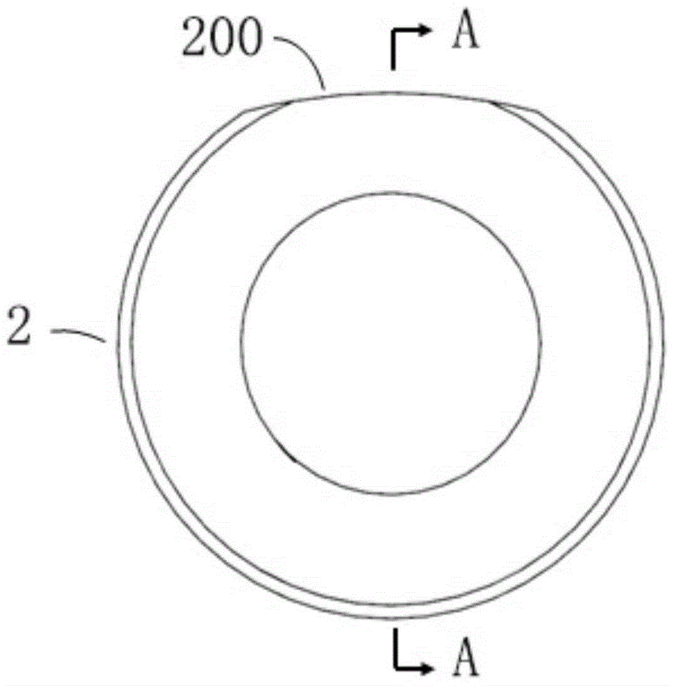
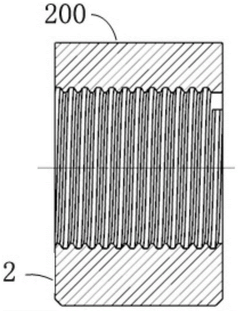
[0043] like Figure 5 and 6 As shown, the cross section of the recessed portion 200 is a convex arc or a concave arc. A transitional arc is provided at the joint between the concave portion 200 and the outer surface of the nut body 2 . During installation, put the locknut between two adjacent shoulders 10 at the end of the wheel 1, both shoulders 10 are ring-shaped, and the locknut is located between the two annular shoulders 10 In the groove, the concave portion 200 is matched with the outer shoulder 10, that is, the concave portion 200 is a convex arc, which has the same curvature as the inner wall of the outer shoulder 10; The loose nut is connected, and the other end is hydraulically stretched and pre-tightened, and then connected with an ordinary nut, and then the ordinary nut is tightened by a mechanical anti-loosening method to prevent falling off. Of course, the recessed part 200 can also be arranged at the place where it meets the inner shoulder 10, and the recesse...

Embodiment 2

[0045] like Figure 7 As shown, the present embodiment is basically the same as the first embodiment, the only difference is that the nut body 2 includes two recesses 200 that are not connected to each other. Preferably, one of the two concave portions 200 is a convex arc, and the other is a concave arc. That is to say, the two concave parts 200 on the nut body 2 are respectively matched with the shoulders 10 on both sides to achieve two anti-loosening effects, and the anti-loosening effect is better; the stress is dispersed, the nut body 2 is not easily deformed, and the anti-loosening effect is good. Preferably, the centers of the two recesses 200 are collinear with the center of the nut body 2 to facilitate processing.

[0046] This embodiment only provides the embodiment in which the concave portion 200 is an outer convex arc and an inner concave arc respectively, and the combination thereof also belongs to the protection scope of the present invention, for example, both ...

Embodiment 3

[0048] like Figure 8As shown, this embodiment is basically the same as the first or second embodiment, the only difference is that one end of the nut body 2 is provided with a stress relief groove 21, and the stress relief groove 21 is a closed annular sinker. That is, an annular groove is arranged at one end of the nut body 2, which is located between the thread of the nut body 2 and the outer surface, as a stress relief groove 21; Therefore, a stress relief groove 21 is provided on its outer side, so that these thread teeth can have a small deformation outward, so as to relieve the force on the thread teeth and prevent the thread teeth from being damaged.

[0049] Preferably, one end of the nut body 2 is opposite to the wheel disc 1 of the gas turbine rotor, and a gasket is provided at the end of the nut body 2 opposite to the wheel disc 1; Washers, spring washers, or a combination of two types of washers; when there is a rounded corner between the shoulder 10 and the whee...


PUM


Abstract

The invention belongs to the technical field of locknuts and discloses a locknut for a rotor of a gas turbine. The locknut comprises a recessed part arranged on the outer side face of a nut body, the distance between any point on the recessed part and the center of the nut body is smaller than the radius of the outer side face of the nut body, and the recessed part penetrates the whole nut body in the radial direction. Through the arrangement of the recessed part penetrating the whole nut body in the radial direction on the outer side of the nut body, the recessed part is matched with a protruding shoulder, and the locking function is achieved. The structure of an existing wheel disc is fully used, the structure is simple, assembly and disassembly are convenient, and the anti-looseness self-locking effect is good. The invention discloses two machining methods of the locknut. Multiple recessed parts can be machined at the same time through a tool rotary disc and linear cutting, and the recessed parts are not limited to the contour shape.

Description

technical field [0001] The invention relates to the technical field of lock nuts, in particular to a gas turbine rotor lock nut and a processing method thereof. Background technique [0002] The peripheral tie-rod rotor of the gas turbine closely fits the discs at all levels through a plurality of tie-rod bolts distributed in the circumferential direction and the nuts matched with them. The tie rod bolts not only play the role of connecting the wheel, but also the radial position of the tie rod hole on the wheel also determines the stiffness of the entire rotor. From the point of view of stiffness, the farther the stay bolts are radially outward from the disc, the better the stiffness of the entire gas turbine rotor will be. [0003] In order to ensure the integrity of the gas turbine rotor, in addition to ensuring sufficient pre-tightening force of tie rod bolts, thread reversal and relaxation caused by tie rod material creep, impact, vibration, variable load, etc. must al...

Claims


Application Information

Patent Timeline
Patent Type & Authority Applications(China)
IPC IPC(8): F16B37/00F16B39/02B23B1/00B23H7/02
Inventor 陈海燕范玮陈宏张传斌刘阔
Owner BEIJING HUAQING GAS TURBINE & INTEGRATED GASIFICATION COMBINED CYCLE ENG TECH
Why Eureka
Try Eureka