Modularization clean room unit device

A clean room, modular technology, used in mechanical equipment, lighting and heating equipment, household heating and other directions, can solve the problems of clean room pollution, inconvenient installation, etc., to achieve compact size, simple installation, good sealing effect

Active Publication Date: 2016-01-27
中国电子系统工程第四建设有限公司
View PDF8 Cites 13 Cited by
  • Summary
  • Abstract
  • Description
  • Claims
  • Application Information

AI Technical Summary

Problems solved by technology

In the traditional clean room, it is necessary to install units such as high-efficiency filter ceiling air supply, side wall return / exhaust air, and purification lamps installed to meet the illumination requirements. Various arrangements are not only inconvenient to install, but also bring more pollution risks to the clean room

Method used


Image

  • Modularization clean room unit device
  • Modularization clean room unit device
  • Modularization clean room unit device

Examples


Embodiment Construction

[0020] The present invention will be further described in detail below in conjunction with the accompanying drawings and specific embodiments.

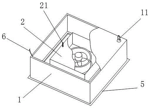
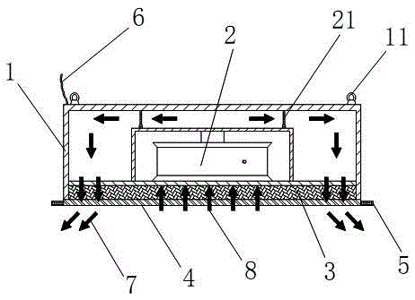
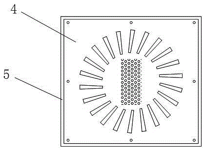
[0021] A modular clean room unit equipment such as Figure 1 to Figure 5 As shown, it includes an outer box body 1, a filter fan, a filter, a diffuser plate 4 and a lighting device 5. The outer box body 1 is a cover with a closed upper end and an open lower end; the diffuser plate 4 is fixedly arranged at the lower end opening of the outer box body 1, and the diffuser plate 4 includes an air supply port and an air return port, and the air return port is located in the middle of the diffuser plate 4. The air inlet is located around the air return port; the top of the diffuser plate 4 is successively provided with a filter and a filter fan; the filter is a high-efficiency filter 3; the filter fan is preferably a medical filter fan 2, and the air inlet of the medical filter fan 2 is aligned with An airflow channel is formed between the ...


PUM


Abstract

The invention discloses a modularization clean room unit device, and relates to the technical field of clean room equipment. The unit device comprises an outer box, a filter draught fan, a filter and a flow scattering plate. The outer box is a cover with the upper closed end and the lower open end. The flow scattering plate is arranged at the opening in the lower end of the outer box. The filter and the filter draught fan are sequentially arranged above the flow scattering plate. The flow scattering plate comprises an air supply port and an air returning port. An air inlet of the filter draught fan is aligned with the air returning port of the flow scattering plate. A channel is formed by an air outlet of the filter draught fan and the air supply port of the flow scattering plate. The device is provided with the filter draught fan, and air supplying and air returning are integrated. The modularization clean room unit device is compact in size, good in sealing performance, easy and convenient to install, reliable and stable in running, capable of saving energy, free of dust generation and dust accumulation, capable of effectively reducing the pollution source of a clean room and wide in application range.

Description

technical field [0001] The invention relates to the technical field of clean room equipment. Background technique [0002] Clean room refers to the removal of particulates, harmful air, bacteria and other pollutants in the air within a certain space, and the control of indoor temperature, cleanliness, indoor pressure, air velocity and air distribution, noise vibration, lighting, and static electricity. Within a certain range of needs, a specially designed room is given. In the traditional clean room, it is necessary to install units such as high-efficiency filter ceiling air supply, side wall return / exhaust air, and purification lamps installed to meet the illumination requirements. Various arrangements are not only inconvenient to install, but also bring more pollution risks to the clean room . Especially in hospitals and pharmaceutical production purification areas, clean room pollution sources should be minimized. Contents of the invention [0003] The technical prob...

Claims


Application Information

Patent Timeline
Patent Type & Authority Applications(China)
IPC IPC(8): F24F3/16F24F13/078F24F13/28
CPCF24F13/078F24F13/28F24F3/167
Inventor 赵伟陈辉唐叶辰赵杨玲
Owner 中国电子系统工程第四建设有限公司
Why Eureka
Try Eureka