
Method for determining a correlated waveform on a real time oscilloscope

A waveform and deterministic technology, applied in the direction of digital variable/waveform display, instrument, external dimension measurement, etc., can solve the problem of wrongly expressing eye opening and so on

Inactive Publication Date: 2016-01-27
TEKTRONIX INC
View PDF4 Cites 4 Cited by
  • Summary
  • Abstract
  • Description
  • Claims
  • Application Information

AI Technical Summary

Problems solved by technology

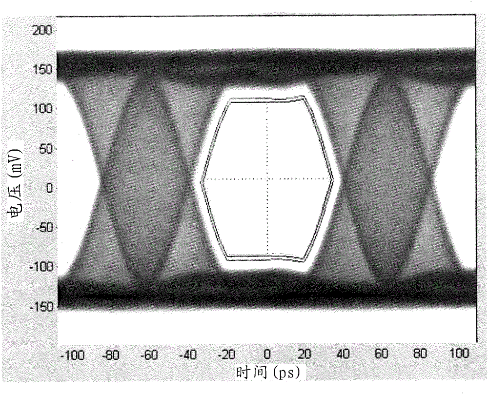
However, in the presence of large periodic jitter, eye diagrams generated based on averaged correlated waveforms may misrepresent the shape of the eye opening

Method used


Image

  • Method for determining a correlated waveform on a real time oscilloscope
  • Method for determining a correlated waveform on a real time oscilloscope
  • Method for determining a correlated waveform on a real time oscilloscope

Examples


Embodiment Construction

[0025] In the drawings, which are not necessarily to scale, similar or corresponding elements of the disclosed systems and methods are denoted by the same reference numerals.

[0026] Refer now figure 1 , Shows a representative block diagram of a real-time oscilloscope according to some embodiments of the present invention for implementing the disclosed technology. Although a real-time oscilloscope is shown and discussed below, any type of test and measurement instrument that can obtain an appropriate representation of the time domain waveform can be used.

[0027] The oscilloscope 100 may have a separate signal channel 102 coupled to the accessory interface 104, figure 1 Two of them are shown in. Each signal channel 102 may have a separate acquisition unit 106, which may include, for example, a known signal for receiving at least an analog waveform input signal from the device or channel under test (such as the probe 122) and converting the received signal into a digital sample. ...


PUM


Abstract

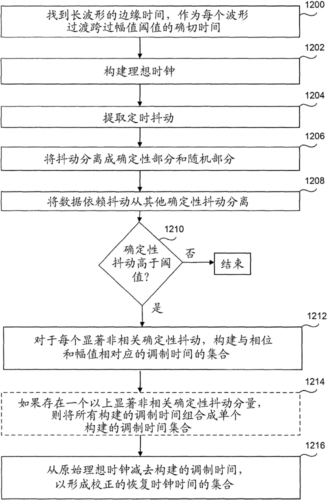
The invention relates to a method for determining a correlated waveform on a real time oscilloscope. A method for determining a correlated waveform, includes acquiring a generalized waveform record with a repeating pattern, determining a possibly corrected recovered clock signal for the generalized waveform record, selecting a new sample rate that is higher than the clock rate by N time, where N is an integer greater than 1, resampling the generalized waveform so that the new samples fall precisely on two clocks instants of the recovered clock signal that define each unit interval, and on N-1 additional instants equally spaced between the two clock instants of each unit interval to create a resampled waveform, and forming the correlated waveform by taking the mean values of all samples from the resampled waveform having the same offset into a pattern repeat in unit intervals or fractions thereof.

Description

[0001] rights and interests [0002] This application claims the benefit of U.S. Provisional Application Serial No. 62 / 026,943 entitled "Method for Determining Related Waveforms on Real-Time Oscilloscopes" filed on July 21, 2014, which is incorporated herein by reference in its entirety. Technical field [0003] The present disclosure relates to generating correlation waveforms corresponding to repeated data patterns in generalized waveforms with improved accuracy in the presence of large deterministic jitter. Background technique [0004] In the field of high-speed serial data communications, eye diagrams have historically been used to assess waveform fidelity and system timing and voltage margins. [0005] In many cases, it is practical to use waveforms that carry periodic repetitive data patterns to evaluate components or systems. The generalized waveform always exhibits both related and unrelated defects. For both eye diagram production and noise / jitter analysis, it is sometimes...

Claims


Application Information

Patent Timeline
Patent Type & Authority Applications(China)
IPC IPC(8): G01R29/04
CPCG01R13/34G01R13/0272G01R31/31709
Inventor M.L.京瑟
Owner TEKTRONIX INC
Learn More