Optical fiber connector

A technology of optical fiber connector and optical fiber, which is applied in the field of optical fiber communication, can solve the problems of optical fiber damage, affecting the accuracy of optical fiber connection, looseness, etc., and achieve the effect of high assembly accuracy, simplified assembly and disassembly

Active Publication Date: 2016-01-27
HONG FU JIN PRECISION IND (SHENZHEN) CO LTD +1
View PDF8 Cites 5 Cited by
  • Summary
  • Abstract
  • Description
  • Claims
  • Application Information

AI Technical Summary

Problems solved by technology

[0003] However, due to the limited clamping force of the existing optical fiber clamping device on the optical fiber, it is easy to make the optical fiber loose relative to the optical fiber clamping device during the retraction, which affects the accuracy of the fiber connection. In addition, due to the fiber clamping device and the fiber ferrule The strength of the connection between them is mainly controlled by the operator's personal experience. Therefore, during assembly, the arching height of the optical fiber is not easy to control, and it is easy to cause damage to the optical fiber due to excessive force of the operator.
In addition, the existing optical fiber connector assembly process is relatively complicated and difficult to disassemble

Method used


Image

  • Optical fiber connector
  • Optical fiber connector
  • Optical fiber connector

Examples


Embodiment Construction

[0019] The optical fiber connector of the present invention will be further described in detail in conjunction with the accompanying drawings and specific embodiments.

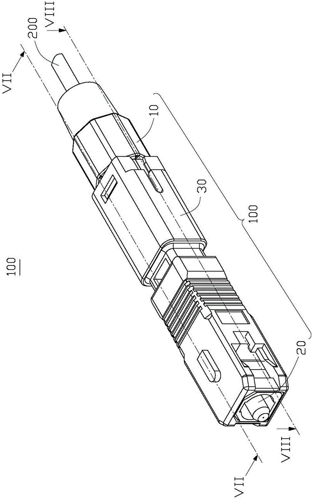
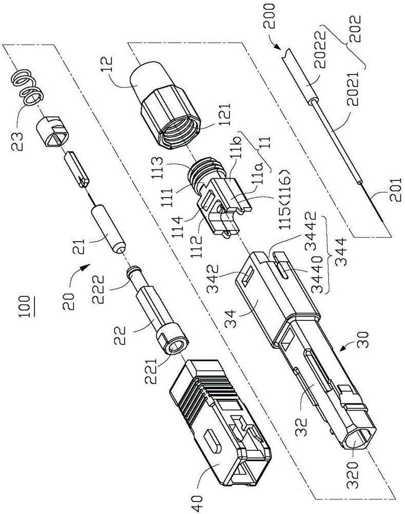
[0020] see Figure 1-3 , the optical fiber connector 100 of the embodiment of the present invention is used to connect the optical fiber 200, and the optical fiber connector 100 includes an optical fiber fixing unit 10, an optical fiber ferrule unit 20, and a fiber optic connector connecting the optical fiber fixing unit 10 and the optical fiber ferrule Housing 30 of unit 20 . The optical fiber 200 includes a core 201 and a cladding layer 202 covering the core 201, the cladding layer 202 is used to protect the core 201, in this embodiment, the cladding layer 202 is further It includes an inner cladding layer 2021 on the inner layer and an outer cladding layer 2022 on the outer layer. When the optical fiber connector 100 is assembled, the cladding layer 202 is peeled off by a predetermined length to expose a c...


PUM


Abstract

An optical fiber connector used for clamping an optical fiber. The optical fiber includes a fiber core and a coating layer that covers the fiber core, and part of the coating layer is stripped from the fiber core to form coating layer strips. The optical fiber connector includes an optical fiber fixing unit, an optical fiber core insertion unit and a shell connecting the optical fiber fixing unit and the optical fiber core insertion unit. The optical fiber fixing unit includes a clamping member that fixedly holds the optical fiber and includes a first clamping part and a second clamping part. One of the first clamping part and the second clamping part includes at least one positioning column, and the other one is provided with at least one positioning hole corresponding to the positioning column. The positioning column is used for winding the coating layer strips thereon, the first clamping part and the second clamping part are mutually fastened to fix the optical fiber therebetween, and the positioning columns are inserted in the positioning holes.

Description

technical field [0001] The invention relates to the field of optical fiber communication, in particular to an optical fiber connector. Background technique [0002] In the field of optical fiber communication, optical fibers are connected to each other or to electronic terminals through optical fiber connectors, and the connection accuracy between optical fiber connectors and optical fibers will directly determine the transmission efficiency of optical signals. Existing optical fiber connectors generally include a fiber ferrule and a fiber clamping device. During assembly, the optical fiber is aligned with the fiber ferrule through the fiber clamping device and has an arch relative to the fiber ferrule, and then the fiber clamping device pulls the fiber back Back and make the optical fiber have a predetermined arch height. [0003] However, due to the limited clamping force of the existing optical fiber clamping device on the optical fiber, it is easy to make the optical fi...

Claims


Application Information

Patent Timeline
Patent Type & Authority Applications(China)
IPC IPC(8): G02B6/38
CPCG02B6/3869G02B6/3888G02B6/245G02B6/3825G02B6/3881
Inventor 卫乐朋栗志明
Owner HONG FU JIN PRECISION IND (SHENZHEN) CO LTD
Why Eureka
Try Eureka