

I-shaped current transformer
A current transformer and I-type technology, applied in the field of transformers, can solve problems such as inconvenient installation, inconvenient on-site installation, and inability to apply on-site, etc., and achieve the effect of reducing weight
- Summary
- Abstract
- Description
- Claims
- Application Information
AI Technical Summary
Problems solved by technology
Method used
Image

Examples
Embodiment Construction
[0015] Below in conjunction with accompanying drawing and preferred embodiment of the present invention, the present invention will be further described:
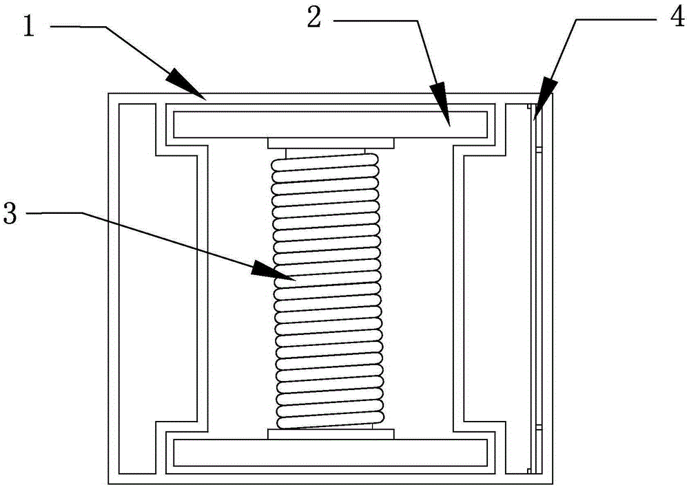
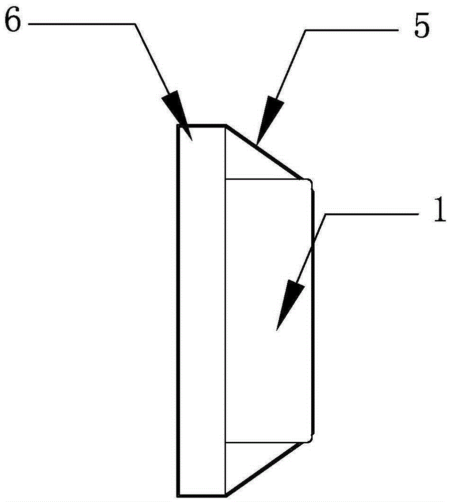
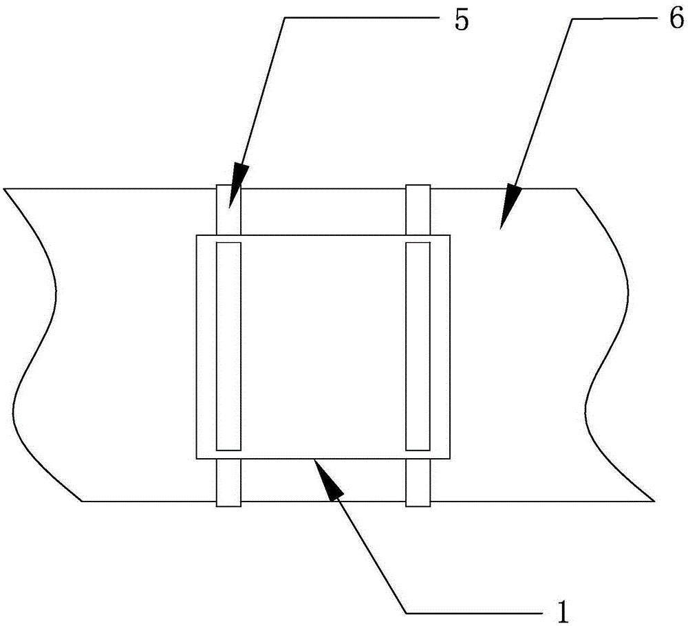
[0016] refer to Figure 1 to Figure 4 , an I-type current transformer, including a housing 1, a magnetic core 2 and a coil 3, the magnetic core 2 is an I-shaped structure, and the coil 3 is wound on the middle connecting rod of the magnetic core 2, and the I-shaped The magnetic core 2 can increase the cross-sectional area of its two sides, so that the area of the coil 3 and the cable current need not be increased, and the magnetic flux passing through the coil 3 can be effectively increased to generate a larger induced current. The magnetic core 2 is made of permalloy material, which has high magnetic permeability and magnetic saturation capability, which can ensure the effective passage of magnetic flux through the magnetic core 2 and gather more magnetic flux to pass through the coil 3 . There are three cavities arra...
PUM
 Abstract
Description
Claims
Application Information