Motor demagnetization method and apparatus

A degaussing method and technology of a degaussing device are applied in the estimation/correction of motor parameters, etc., and can solve the problems of low reliability of software speed tracking

Active Publication Date: 2016-01-27
SUZHOU WEICHUANG ELECTRICAL EQUIP TECH
View PDF6 Cites 7 Cited by
  • Summary
  • Abstract
  • Description
  • Claims
  • Application Information

AI Technical Summary

Problems solved by technology

[0003] The purpose of the present invention is to provide a motor degaussing method and device, aiming to solve the problem in the prior art that the soft

Method used


Image

  • Motor demagnetization method and apparatus
  • Motor demagnetization method and apparatus
  • Motor demagnetization method and apparatus

Examples


Embodiment Construction

[0038] In order to make the object, technical solution and advantages of the present invention clearer, the present invention will be further described in detail below in conjunction with the accompanying drawings and embodiments. It should be understood that the specific embodiments described here are only used to explain the present invention, not to limit the present invention.

[0039] In order to illustrate the technical solutions of the present invention, specific examples are used below to illustrate.

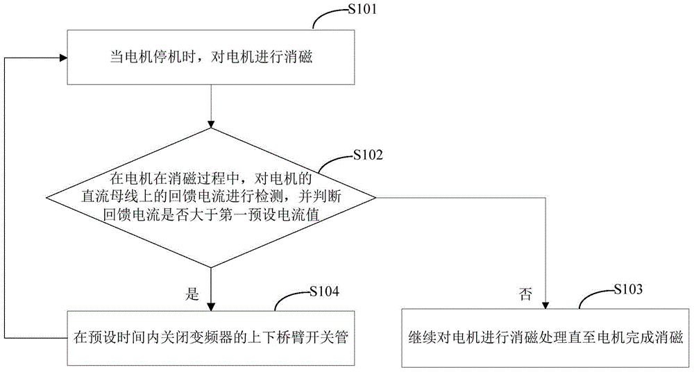
[0040] An embodiment of the present invention provides a motor degaussing method, such as figure 1 As shown, the motor degaussing method includes the following steps:

[0041] S101. When the motor stops, demagnetize the motor;

[0042] S102. During the degaussing process of the motor, detect the feedback current on the DC bus of the motor, and judge whether the feedback current is greater than the first preset current value;

[0043] S103. When the feedback current is...


PUM


Abstract

The invention relates to the technical field of motor demagnetization and provides a motor demagnetization method and apparatus. The motor demagnetization method comprises the following steps of: demagnetizing a motor when the motor is shut down; in a motor demagnetization process, detecting feedback current on a DC bus of the motor and determining whether the value of the feedback current is greater than a first preset current value; when the value of the feedback current is less than the first preset current value, continuing demagnetizing the motor until the demagnetization of the motor finishes; when the value of the feedback current is greater than the first preset current value, switching off the switch tubes of the upper bridge arm and the lower bridge arm of a frequency converter within preset time, and executing the above steps cyclically until the demagnetization of the motor finishes. The method and the apparatus achieve controllable motor demagnetization time and current and may manually set demagnetization time as required. The demagnetized motor fast enters a rotating speed tracking state and thus, not only is rotating speed tracking waiting time shorten, but also the reliability of rotating speed tracking is improved.

Description

technical field [0001] The invention relates to the technical field of motor demagnetization, in particular to a method and a device for motor degaussing. Background technique [0002] When using a frequency converter to drive an asynchronous motor to start, it is possible that the motor is in a rotating state. If the inverter starts normally at this time, it will cause faults such as overcurrent or overload due to excessive slip. Therefore, the frequency converter is equipped with a speed tracking function, which is to detect the actual speed of the motor through the hardware circuit, and start from this frequency. However, adding the above-mentioned hardware circuits will increase the cost, especially for low-power and low-priced machines, which will take up a lot of cost. In addition, adding the above-mentioned hardware circuits will also increase interference during board layout, making the equipment unable to operate normally. In order to solve the above problems, man...

Claims


Application Information

Patent Timeline
IPC IPC(8): H02P23/14
Inventor 刘颖钊
Owner SUZHOU WEICHUANG ELECTRICAL EQUIP TECH
Why Eureka
Try Eureka